
/ KNOWLEDGE · SOURCING
Large part injection moulding — what “large” really means, in numbers
“Can you mould a big part?” is the wrong question — because “big” is not a feeling, it is three numbers: projected area, flow length and shot weight. Those three decide the clamp tonnage, the gating plan and the machine your part needs, and they are computable before you ever email a moulder. This page teaches the arithmetic the way the engineering handbooks teach it, then tells you our own window honestly — including where it ends. Run your part through it and you will know, in ten minutes, which moulders to even shortlist.
First number: projected area sets the clamp
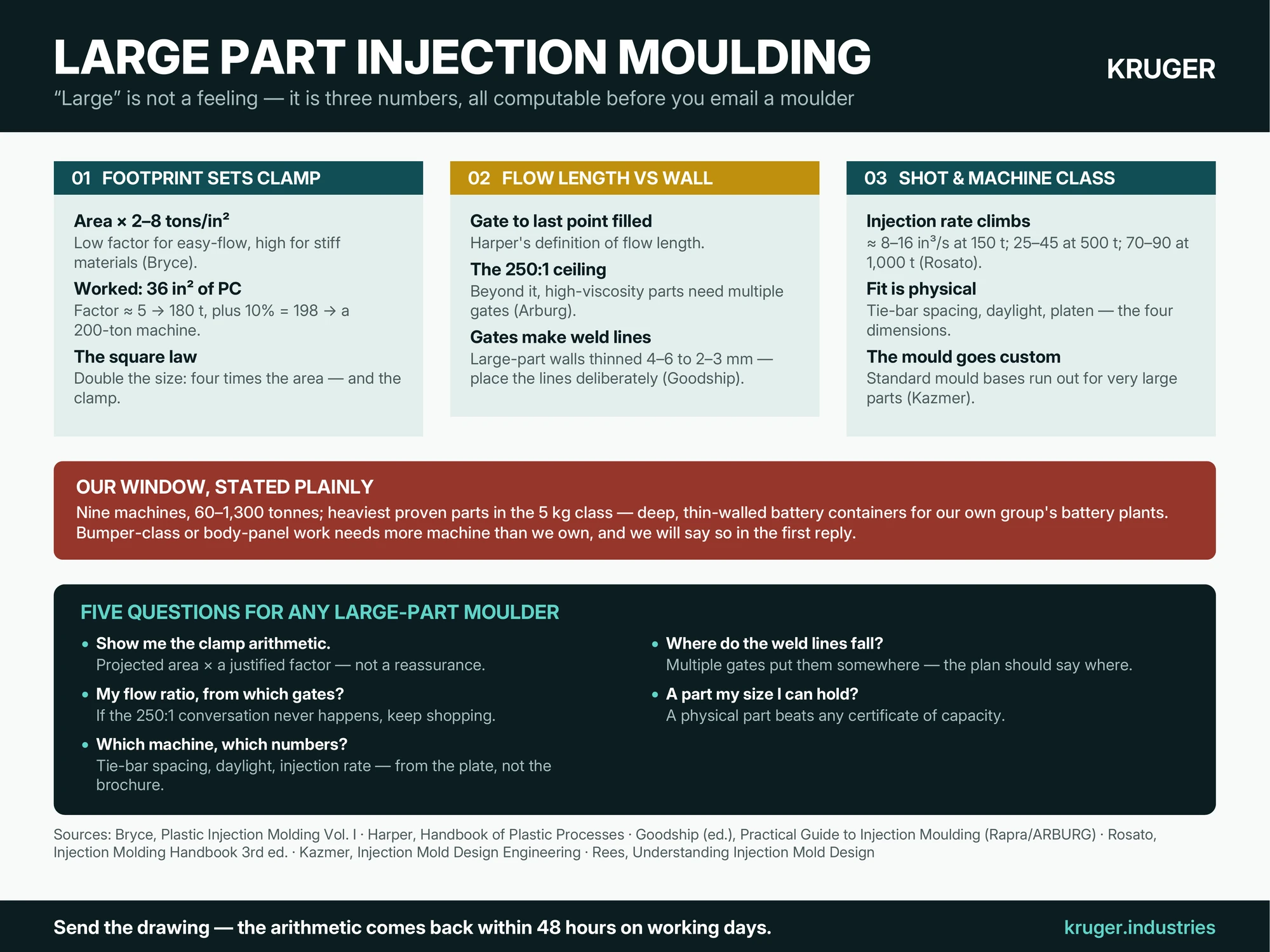
Bryce’s SME handbook does this with a worked example: a part presenting 36 in² (232 cm²) of projected area needs that area multiplied by a clamp factor “of between 2 and 8 tons per square inch” — “the lower numbers… for high-flow materials and the higher numbers… for low-flow (stiff) materials”. Stiff-flowing polycarbonate earns a factor of about 5, giving 180 tons, plus ten percent safety: 198 — so a 200-ton machine. The lesson scales without mercy: double a part’s linear size and its area quadruples, and so does the clamp. A large part is large because of its footprint, not its weight. Put your own footprint through the clamping-force calculator and you have the first machine filter.
Second number: flow length against wall thickness
Harper defines flow length as “the distance from the gate to the last section of the part to be filled”. Melt does not travel forever: the Arburg guide’s flat rule is that the flow-path to wall-thickness ratio “should not exceed 250/1 with high viscosity materials; multiple injections are required if this is the case”. A 500 mm panel at 2 mm walls is already at 250:1 from a central gate — which is why large parts so often carry several gates, and why Harper notes edge gates are “used most often in large part designs” while single-cavity large tools lean on sprue gates. More gates mean more gate-plan decisions and more weld lines: the troubleshooting literature records large-part walls thinning from 4–6 mm to 2–3 mm across the industry, with weld and flow lines growing more visible exactly as cosmetic standards rise. Gate position on a large part is a design meeting, not an afterthought.
Third number: shot weight — and the machine behind it
The shot-size arithmetic must land inside a machine’s honest window, and big machines differ by more than size: Rosato’s tables show injection rate climbing with machine class — roughly 8–16 in³/s for a 150-ton machine, 25–45 for a 500-ton, 70–90 for a 1,000-ton — “if the injection rate did not increase with injection-unit shot size, large parts would have to have even thicker walls” to fill before freeze-off. Tie-bar spacing, daylight and platen size then decide whether the mould physically fits: the machine guide walks those four dimensions. The mould itself changes character too — Kazmer notes that for very large parts, standard mould bases “may not be available as a standard product”, so the tool becomes a custom build, with everything that means for tooling cost and timeline; Rees illustrates the result with a large moulding fed by six edge gates off a hot-runner system. Large parts also tend to run one cavity at a time — the economics are in the cavities guide.
Our window, stated plainly
Kruger runs nine machines from 60 to 1,300 tonnes, and our heaviest proven parts are in the 5 kg class — deep, thin-walled battery containers and lids moulded for the battery factories in our own group, which is large-part work by every test above: big footprint, long flow paths, multi-wall boxes that must come out flat. That is our honest range. A bumper-class or body-panel-class part needs more machine than we own, and if your part is one of those we will say so in the first reply and lose gracefully. What we will not do is squeeze a large part into a small machine — under-clamped tools flash, over-stretched flow paths starve, and both failure modes are written up in our defects guide.
Five questions for any large-part moulder
- What clamp does my part need, shown as arithmetic? Projected area × clamp factor, with the factor justified by the material’s flow — not a reassurance.
- What is my flow-path-to-wall ratio, and from which gate positions? If the answer ignores the 250:1 conversation, keep shopping.
- Which machine will it run on, and what are that machine’s tie-bar spacing, daylight and injection rate? Numbers from the plate, not the brochure.
- Where will the weld lines fall, and are they acceptable on my cosmetic faces? Multiple gates put them somewhere — the plan should say where.
- Has this moulder run parts of my footprint before — and can I see one? A physical part beats any certificate of capacity.
If your part lives anywhere in the 60–1,300-tonne world, send the drawing — an engineer replies within 48 hours on working days with the arithmetic done, including when the honest answer is “not us”. And for the full checklist on judging any moulder, take the supplier-qualification guide.
Sources quoted: V. Goodship (ed.), Practical Guide to Injection Moulding (Arburg / Rapra Technology, 2004); C. A. Harper (ed.), Handbook of Plastic Processes (Wiley, 2006); D. V. Rosato, D. V. Rosato and M. G. Rosato, Injection Molding Handbook, 3rd ed. (Kluwer Academic, 2000); D. M. Bryce, Plastic Injection Molding, Vol. I (Society of Manufacturing Engineers, 1996); D. O. Kazmer, Injection Mold Design Engineering (Hanser, 2007).