
/ KNOWLEDGE · QUALITY
Flash in injection moulding — a buyer’s guide
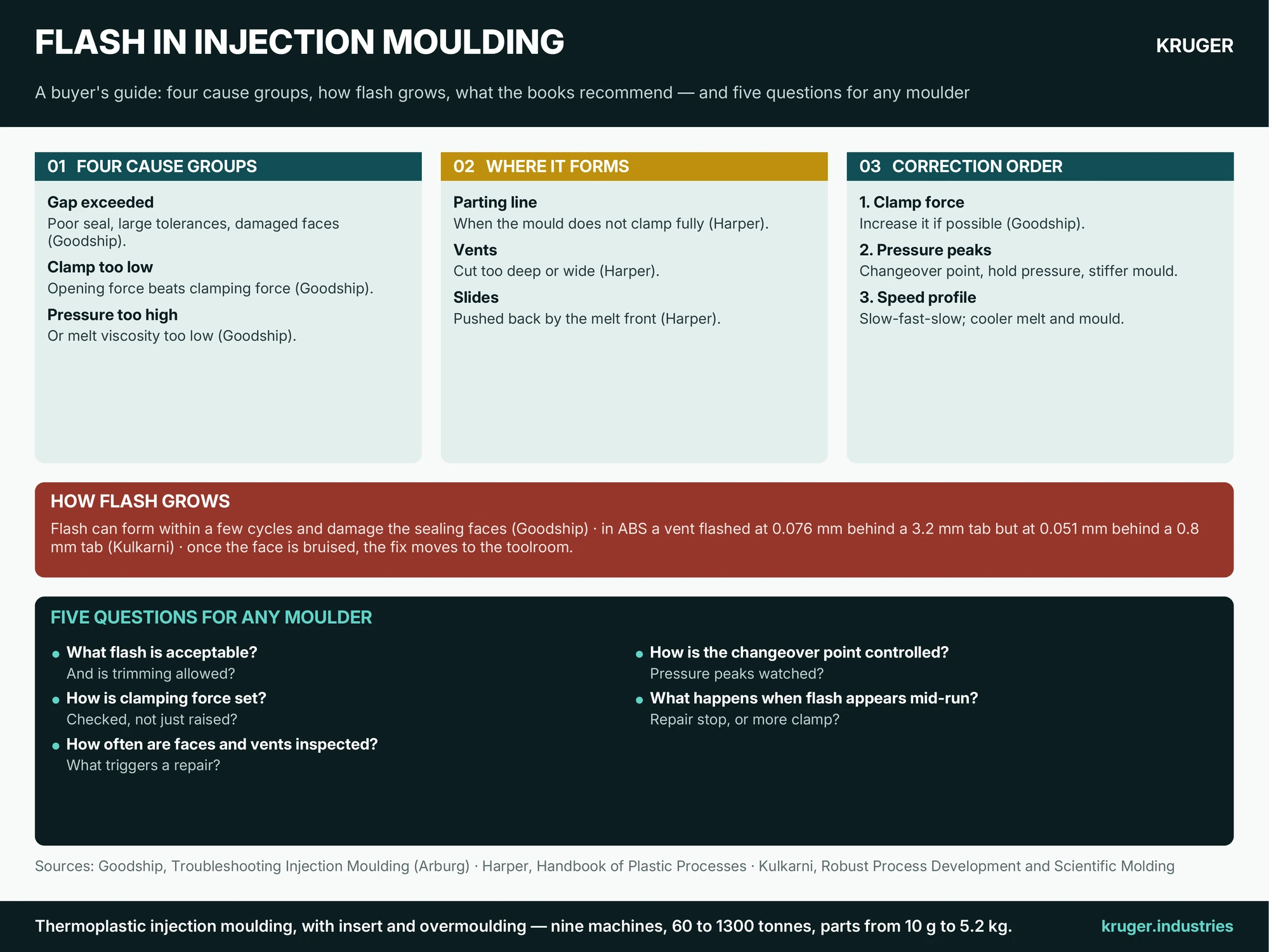
Flash is a thin film of plastic where there should be none, and it is the defect that most often points at the tool or the press rather than at a setting. The buyer’s interest is simple: flash that is trimmed away every cycle is a cost, flash that grows is a warning, and flash left on the part is a rejection. Goodship describes it as a film-like edge that often forms near sealing faces, vent channels, ejectors and joins in the mould, and adds that fine flash is not always visible at once while thick flash can stand out several centimetres. This page covers the four cause groups, how flash grows, what the books recommend, and five questions for any moulder. See also our guide to moulding defects.
The four cause groups
Goodship divides the causes of flash into four:
- The allowed gap is exceeded. The mould does not seal well enough, production tolerances are too large, or the sealing faces are damaged.
- Clamping force is insufficient or set too low. The mould-opening force is higher than the clamping force, so the mould cannot be kept closed, or the clamping force deforms the platens and the mould.
- Internal mould pressure is too high. The shaping pressure at the gap is high enough to push melt into very small gaps.
- Viscosity is too low. High internal pressure and low flow resistance together favour flash.
Harper locates it the same way: the parting line is the commonest place, where the mould does not clamp fully; vents are another, especially if cut too deep or wide; and movable sections such as slides can be pushed back by the melt front, letting material flash into the gap. Our guides cover the setting of clamping force and the depth of mould vents.
Whose problem is it?
Read against Goodship’s four groups, flash has three possible owners: the press (clamping force too low, platens deflecting), the tool (damaged sealing faces, worn slides, oversize vents) and the process (internal pressure too high, a melt that is too thin). A moulder who answers a flash complaint only by raising the clamp setting has addressed one owner of the three. The buyer’s reading, not a book claim, is that the useful answer names which owner was found at fault.
How flash grows
Goodship warns that flash can form within a few cycles and damage the sealing faces, which is why a recurring flash problem cannot be left alone. Once the parting face is bruised, the gap exists whatever the setting, and the fix moves from the operator to the toolroom. Kulkarni’s vent study shows the same dependence on geometry: the vent that was safe against a thick section flashed against a thin one, because pressure rises as plastic is forced into thinner sections. In his tests with an ABS, tabs 3.2 mm thick flashed at a vent depth of 0.076 mm, while 0.8 mm tabs flashed at 0.051 mm. He adds that mould makers keep vents at the lower end of the recommendation for exactly this reason. Thin melts flash first: the published vent depth for nylon is only about 0.013 to 0.017 mm, against 0.05 mm for ABS (Kulkarni), which is why a vent that suits one material floods on another.
What the books recommend
Goodship’s correction chart works through the groups in order:
- Can clamping force be increased? If so, increase it.
- Is the mould deforming? Avoid pressure peaks: optimise the changeover point, reduce holding pressure, change the clamping force, stiffen the mould.
- Is the flash near the gate? Lower the injection speed, or use a slow-then-fast profile.
- Otherwise, change over to holding pressure earlier, lower injection speed with a slow-fast-slow profile, and reduce melt and mould wall temperature.
Two lessons follow. Clamping up is only the first step, and it is the one that hides tool wear; the chart goes on to pressure peaks and mould stiffness. And the changeover point matters: pressure that overshoots at the switch from filling to holding is a classic source. Our guide to scientific moulding shows how a study sets that point, and the mould maintenance guide covers the care of sealing faces.
Five questions for any moulder
- What flash is acceptable, where, and is trimming allowed? Put the maximum on the drawing, because manual deflashing can touch dimensions.
- How is clamping force set, and is it checked against the projected area rather than simply raised?
- How often are parting faces, slides and vents inspected, and what finding triggers a repair?
- How is the changeover point controlled, and is pressure overshoot watched?
- What happens when flash appears mid-run: a repair stop, or a higher clamp setting?
Send the part drawing and mark where flash cannot be tolerated, and we will go through these questions with you.