
/ KNOWLEDGE · TOOLING
Mould venting and burn marks — where the air goes before the plastic arrives
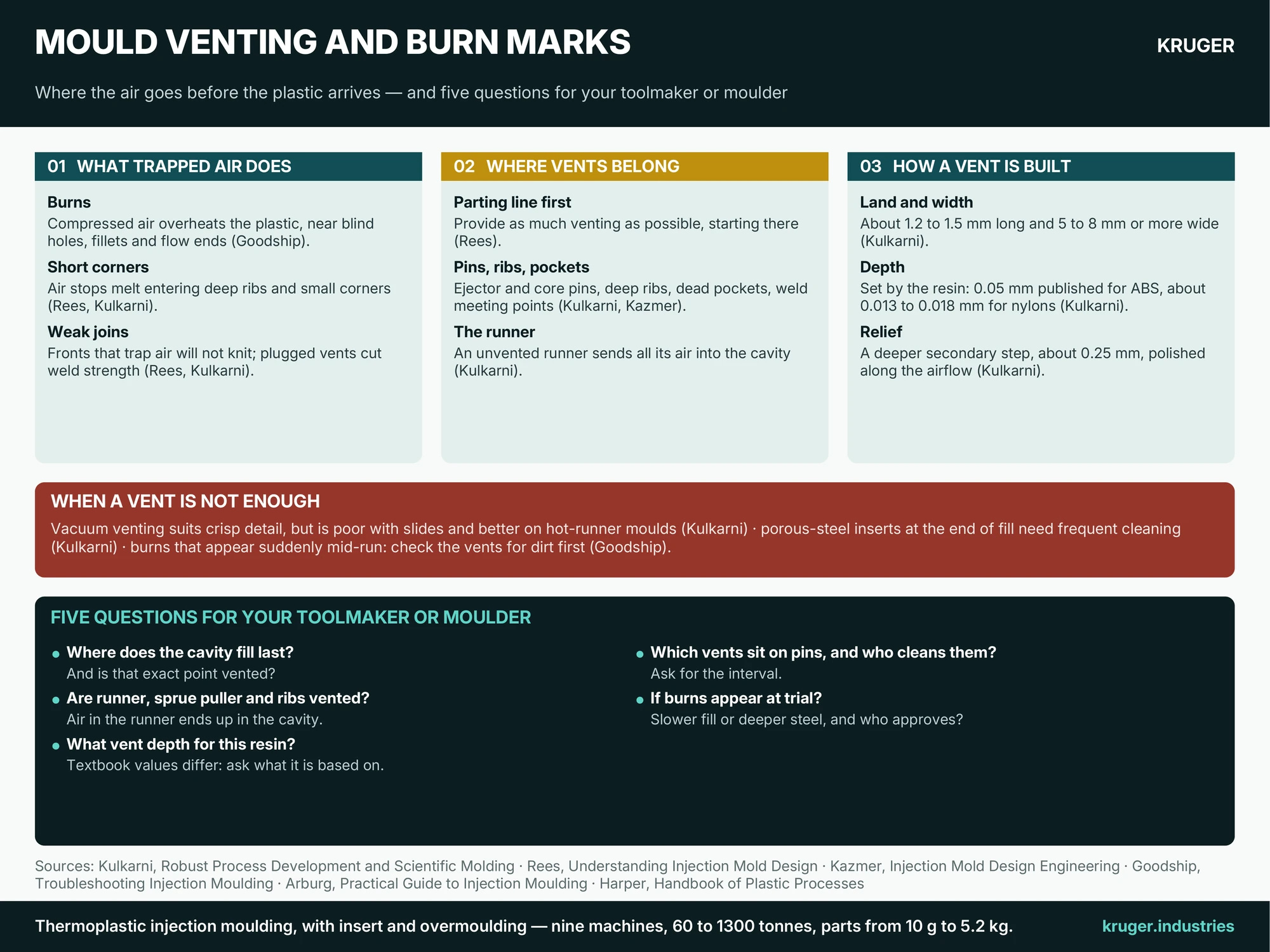
Every cavity is full of air before the plastic arrives, and that air has to leave through gaps thinner than a sheet of paper. When it cannot, it is squeezed ahead of the melt and heats as it is compressed. Rees explains the mechanism: the faster the plastic enters, the more the trapped air is compressed, until it scorches the plastic or blocks a corner. Goodship’s troubleshooting guide calls the resulting burn the diesel effect and treats it as a venting fault, not a material fault. Because vents are cut into the steel when the tool is made, venting is a tooling decision, not a machine setting. Here is what trapped air does, where vents belong, how small they are, and five questions for any toolmaker or moulder. It sits beside our tooling guide and our guide to moulding defects.
What trapped air does to a part
- Burns. Goodship places the diesel effect near blind holes, fillets, the ends of flow paths and wherever several flow fronts fuse. Burnt plastic can also release decomposition products that attack the mould surface.
- Unfilled or rounded corners. Air that cannot leave stops the melt entering deep ribs and small corners. Kulkarni shows a rib left incomplete for lack of venting, and notes that a trapped corner may show only as a rounded edge.
- Weak joins. Rees warns that where two fronts collide and trap air, the plastic will not knit and may even leave a hole. Kulkarni adds that plugged vents also lower weld-line strength.
- Surface faults and voids. Arburg lists trapped air and gases among the causes of short shots, scorching, ripples or depressions in the part and, in extreme cases, etching of the mould; Kulkarni shows voids disappearing once vents were added.
Where vents belong
Kulkarni’s rule is that the most effective vent sits where the part fills last. One vent there would need to be as large as the gate, and plastic would escape through it during packing, so vent area is spread around the mould. Rees’s first rule is to provide as much venting as possible, starting at the parting line.
- Parting line. The easiest place to vent, and the first (Rees, Kulkarni).
- Ejector pins, core pins and inserts in the path of the melt. Kulkarni prefers ejector pins because they clean themselves as they move, though the residue builds up elsewhere in the ejector box.
- Deep ribs and bosses, unless the rib ends at the parting line (Rees).
- Where fronts meet and in dead pockets. Kazmer names three vent locations: the parting plane, the weld line, and dead pockets where melt converges.
- The runner and sprue puller. An unvented runner pushes its whole volume of air through the gate into the cavity (Kulkarni), which overloads the cavity vents. Flash on a runner does not matter, because the runner is scrap.
Geometry can create the problem. In Kazmer’s worked container the melt races round the side walls and forms a weld line and a gas trap opposite the gate. A side-wall gas trap is hard to vent, so a burn there is likely.
How small a vent is
A vent is a shallow step cut at the mould face: deep enough to pass air, shallow enough that plastic cannot follow. Kulkarni describes a primary vent next to the cavity with a land of about 1.2 to 1.5 mm and a width of at least 5 to 8 mm, then a deeper secondary relief of about 0.25 mm leading to the atmosphere, all polished in the direction of airflow. Rees suggests a land of 1.5 to 2.0 mm.
Depth is the delicate figure, because it depends on how readily the resin flows. Kulkarni quotes published values of about 0.05 mm for ABS and roughly 0.013 to 0.018 mm for nylons, while Rees mentions gaps of about 0.01 mm as common. Textbooks therefore differ, which is the point: ask for the depth chosen for your resin, not a general figure. Kulkarni also reports a test in which ABS began to flash at 0.076 mm behind a thick 3.2 mm section but at 0.05 mm behind a 0.8 mm section, because thin sections raise melt pressure. Toolmakers lean shallow, since a vent cut too deep must be welded and re-cut, so a first trial may burn and the cure be a deeper vent.
When a vent is not enough
Kulkarni describes vacuum venting for cavities where detail must be crisp and ordinary vents have failed. It needs a seal around the cavity, so moulds with slides are poor candidates and cold-runner moulds leak; valve-gate and hot-runner moulds suit it better. Porous-steel inserts at the end of fill do a similar job in deep parts where a pin will not fit (Kulkarni, Arburg, Harper), but they need frequent cleaning and cannot take a mirror finish.
Vents also clog. Goodship’s flow chart for burns begins with a question: did the fault appear suddenly during production? If so, check the venting channels for dirt first. Its other remedies are a slower injection speed, a changed flow profile and, where safe, less clamp force, which cost cycle time or risk flash.
Five questions for your toolmaker or moulder
- Where does the cavity fill last, and is that point vented?
- Are the runner, sprue puller and deep ribs vented too?
- What vent depth is cut for this resin, and what is it based on?
- Which vents sit on ejector or core pins, and how often are they cleaned?
- If burns appear at trial, is the first answer a slower fill or deeper steel, and who approves the change?
Gate position decides where fronts meet, so read our guide to injection moulding gates alongside this one. Send the part drawing and we will go through these questions with you before any tooling decision is made.