
/ KNOWLEDGE · TOOLING
Ejection in injection moulding — pins, sleeves, strippers and air
Ejection is the last thing a mould does and the first thing a buyer sees go wrong: a pin mark on the visible face, a part that sticks, a part that arrives bent. The books agree on who owns it. Rees says reliable ejection is entirely the responsibility of the mould designer, and that nearly every mould can be designed so the part cannot hang up. This page covers the ejection methods, how pin position and length decide what the part looks like, the machine-fit checks, what causes marks and distortion, and five questions for any moulder. It sits beside our mould design review guide.
The methods
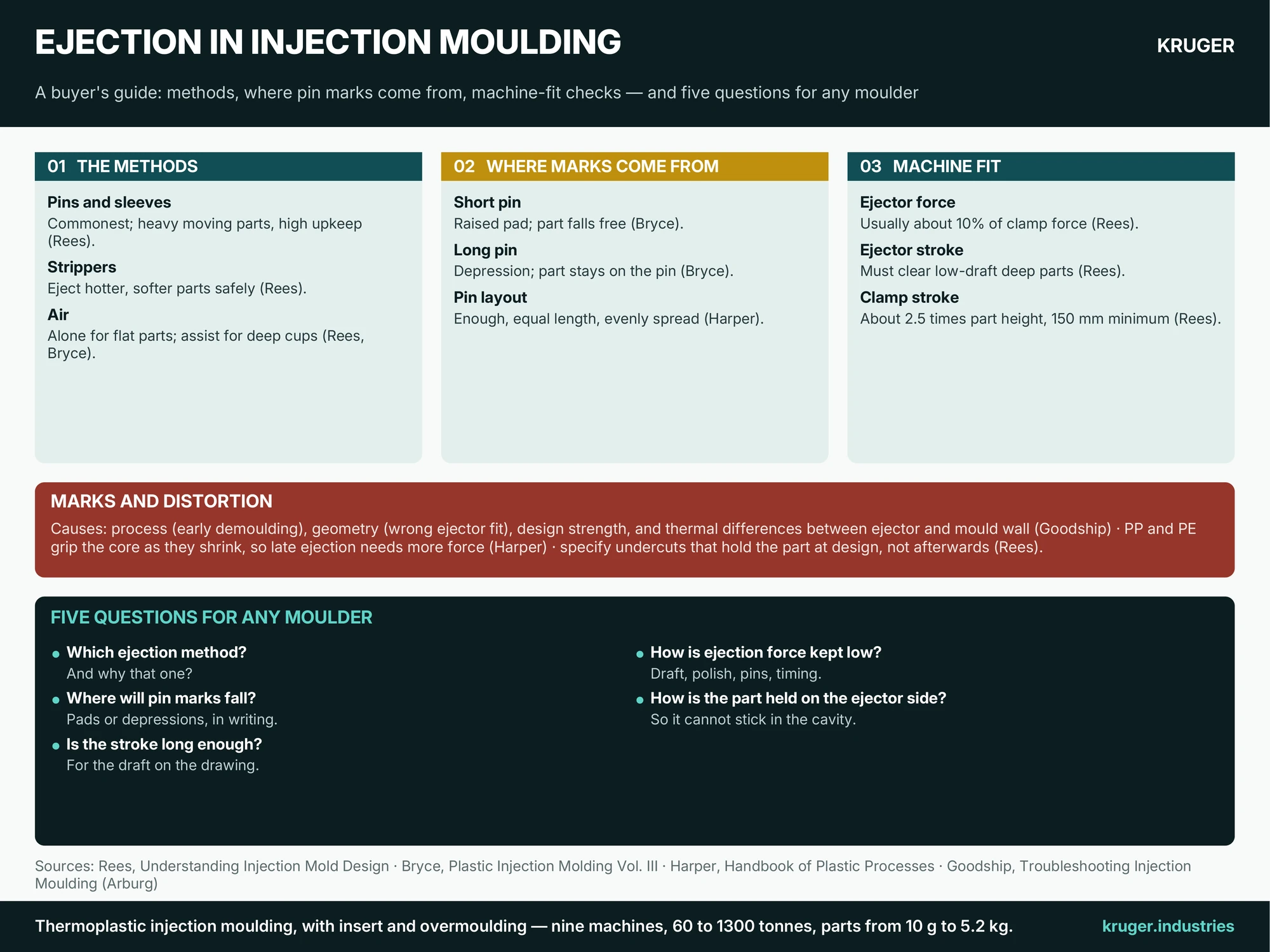
Rees lists pin and sleeve, stripper plate or stripper ring, air alone, air assist, unscrewing, and combinations with robots. Pins and strippers are the oldest and commonest and can serve most plastics, but they have heavy moving parts and the upkeep is high. Air alone suits flat products and, for deep cups, only certain plastics and shapes; its attraction is almost no moving parts. Bryce adds that compressed air is often paired with a standard system for deep-draw parts, with poppet valves in the core letting air in between part and core, and that this needs exact timing. Early ejection shortens the cycle: Rees notes that stripping allows hotter, softer parts to be ejected without damage, while unscrewing needs the parts to be stiffer.
Where the marks come from
Bryce explains the pin mark with a simple fact: a pin cannot be exactly flush with the cavity once tolerances, stack-ups and thermal expansion are counted, so it is made slightly short or slightly long. A short pin leaves a raised pad on the part but lets it fall free; a long pin leaves a depression, and the part tends to stay on the pin. If neither mark is acceptable, he says, another ejection method may be needed. Bryce also wants pins as large in diameter as possible, so ejection force is spread and punctures or cracks are avoided. Harper adds the placement rules: enough pins, all the same length, spread so force is even across the ejector plate, and avoiding areas that resist ejection. Our guide to surface finish covers how a visible face is specified.
Checks that tie the mould to the machine
- Machine ejector force. Rees says it is usually about 10% of the clamping force, enough for most moulds, but some need extra hydraulic or air actuators. Its size and pattern follow the machine builder’s standard.
- Ejector stroke. It must be long enough to push the part fully off the core, especially for deep-draw containers with little draft (Rees).
- Clamp stroke. Rees suggests about 2.5 times the product height, and not less than about 150 mm, so the part can fall clear and the mould faces can be reached for service.
- Return pins bring the ejector plate home as the mould closes (Bryce).
Our guides to the injection moulding machine and to clamping force explain the machine side.
Marks and distortion
Goodship sorts visible ejector marks into process causes such as premature demoulding, geometric causes such as a wrongly fitted or wrongly sized ejector, mechanical causes in the design of mould or part, and thermal causes such as a large temperature difference between the ejector and the mould wall. Deformation at demoulding comes when the force needed cannot be applied without damage, or the movement is disturbed, as with undercuts released without a slide; she says the demoulding force should be kept small, and that shrinkage affects it directly. Harper notes that polypropylene and polyethylene grip the core as they shrink, so a part ejected late needs more force; Harper also reports that a vacuum under a core can resist ejection, and that an air poppet in the core has worked well. Rees adds that undercuts meant to keep a part on the ejector side should be specified at design, not added by the moulder after problems appear. See our guide to undercuts and the draft angle calculator.
Five questions for any moulder
- Which ejection method, and why?
- Where will pin marks fall, and will they be pads or depressions? Agree this in writing for visible faces.
- Is the ejector stroke long enough for the draft on the drawing?
- How is ejection force kept low: draft, polish, pin count and size, ejection timing?
- How is the part held on the ejector side so it cannot stick in the cavity?
Send the part drawing and mark the faces that must stay clean, and we will go through these questions with you.