
/ KNOWLEDGE · PROCESS
Cooling time in injection moulding — the part of the cycle you actually pay for
Every quote you receive for a moulded part is, underneath, a cycle time multiplied by a machine rate — and most of that cycle is cooling. Injection takes a second or two; the mould opens and closes in a few more; the rest is plastic sitting in steel losing heat until it is stiff enough to eject. This guide explains what sets cooling time, why the number on a machine screen understates the real one, and how a buyer checks a quoted cycle before a tool exists. Our cycle-time calculator gives you the number; this page tells you what is behind it.
Where the cycle goes
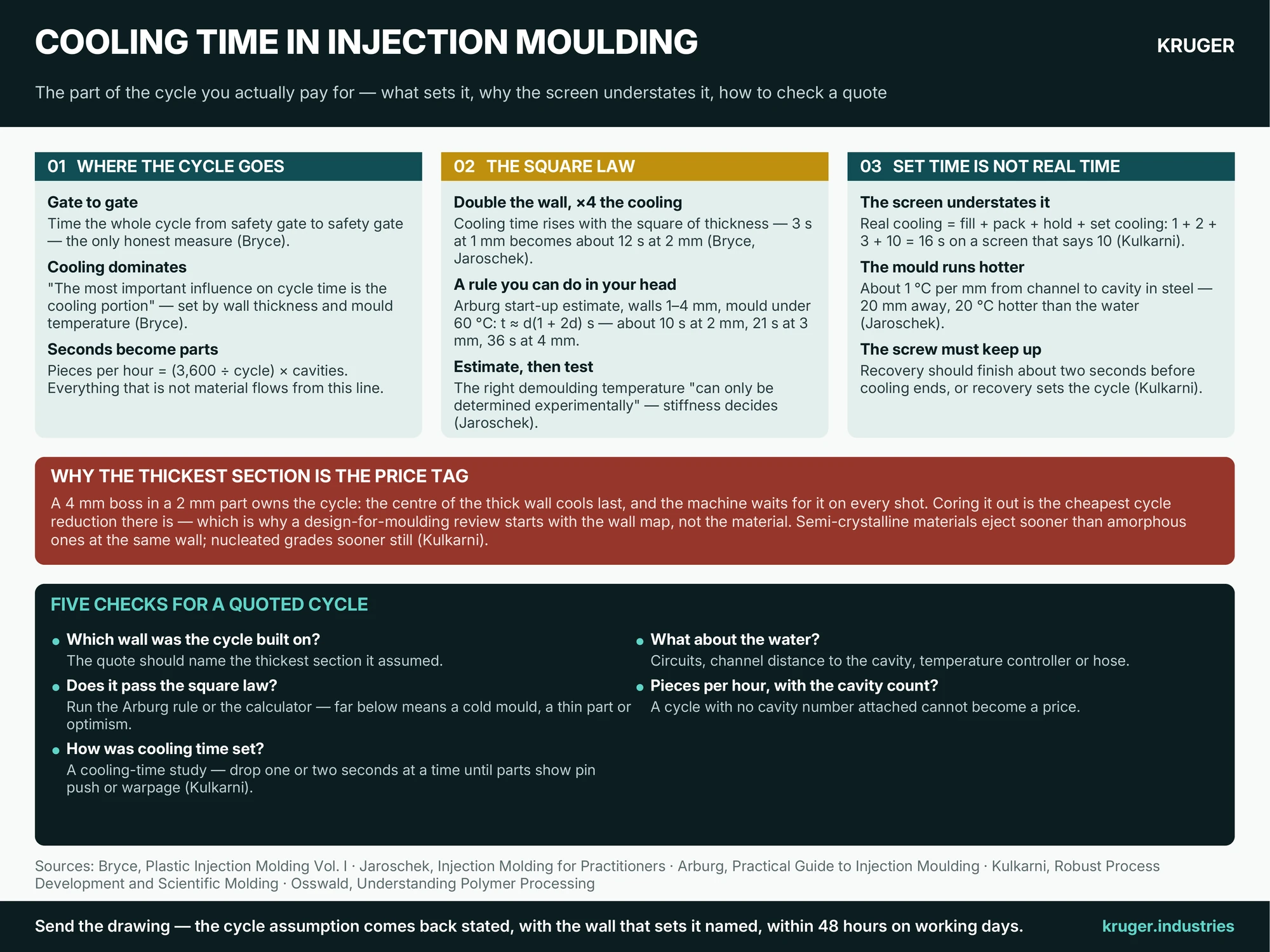
Arburg’s practical guide lists what a cycle is made of: machine and mould movement, mould opening and ejection, mould closing, injection-unit movement, injection time, holding-pressure time and residual cooling time. Bryce measures it the honest way — “gate to gate”, from the moment the operator closes the safety gate to the moment it closes again — and is blunt about which piece matters: “The most important influence on cycle time is the cooling portion of the cycle.” Everything else is seconds; cooling is tens of seconds, and it is set “primarily by the average wall thickness of the part and the temperature at which the mold is maintained”. Bryce also notes that a two-second drift on a thirty-second cycle costs a moulder real money every year — which is why a serious shop times its cycles, and why a serious buyer asks how a quoted cycle was arrived at. The arithmetic that turns the cycle into output is simple: pieces per hour = (3,600 ÷ cycle in seconds) × cavities. Everything in your piece price that is not material flows from that line — the process guide walks the whole cycle phase by phase.
The square law: double the wall, quadruple the cooling
Plastic is a poor conductor, so heat leaves a wall through its two faces and the centre cools last. The consequence, in Jaroschek’s words: “The cooling time increases quadratically with the wall thickness” — change the wall by a factor of two and the cooling time changes by a factor of four. Bryce gives the same rule as a worked case: a wall of 1 mm that cools in 3 seconds needs about 12 seconds at 2 mm. The textbook plate-cooling equation (Osswald’s Eq. 6.3 is the form our calculator runs, with typical thermal data per material) says the same thing with a logarithm attached; Jaroschek simplifies it by inserting plausible values (melt about 200 °C, mould about 20 °C, demoulding about 60 °C, thermal diffusivity about 0.08 mm²/s for plastics) to give a quick estimate from wall thickness alone. Arburg’s start-up rule is the one you can do in your head: for walls of 1–4 mm and mould temperatures under 60 °C, cooling time in seconds is roughly the wall in millimetres multiplied by (1 + 2 × wall); above 60 °C add 30%. Evaluated, that is about 10 s at 2 mm, 21 s at 3 mm and 36 s at 4 mm — a start-up estimate, not a quote, but it shows why the wall-thickness guide treats the thickest section of a part as its price tag. Two honest caveats from Jaroschek: the equation assumes the mould stays at constant temperature, which it does not, and the “right” demoulding temperature “can only be determined experimentally”, because what matters is whether the part is stiff enough to survive ejection — a ribbed part is stable warmer than a flat one.
Set cooling time is not real cooling time
Here is the reading error that makes moulders and buyers talk past each other. On the machine, “cooling time” is a timer that starts after holding pressure ends. But the plastic starts cooling the instant it touches steel, so Kulkarni’s scientific-moulding text defines the real figure as “the addition of the injection time (fill time), set pack time, set hold, and set cooling time” — in his example, 1 + 2 + 3 + 10 = 16 seconds of cooling, on a screen that says 10. Jaroschek makes the same point from the other side: the holding-pressure time “is already part of the cooling time”, so a moulder who lengthens hold without shortening the set cooling time is simply lengthening the cycle. Two more things stretch a cycle beyond theory. First, the mould warms up in cyclic running: Jaroschek reports that in steel moulds “a temperature increase of 1 °C/mm between the cooling channel and the cavity wall is normal”, so a cavity 20 mm from its channel runs about 20 °C hotter than the water — which is why “longer cooling times than theoretically calculated are often necessary” and why cooling-channel layout is a tooling decision with a piece-price consequence. Second, the screw has to recover the next shot while the part cools: Kulkarni’s rule is that recovery must finish “approximately two seconds before the cooling time is reached”, or recovery, not cooling, sets the cycle. Material matters too: for the same wall, a semi-crystalline material can be ejected sooner than an amorphous one, because once its crystallites have formed the part has its stiffness, and nucleated grades shorten that further — the thermoplastics guide explains the divide, and the temperature chart gives the mould temperatures each material wants. The runner cools on the same clock: Bryce notes that sprue and runner need not reach the part’s rigidity, but must be “rigid enough for ejection”, so a fat cold runner can hold a thin part hostage — the gates guide covers the trade.
How to check a quoted cycle before the tool exists
- Ask which wall the cycle was built on. A quote should name the thickest section it assumed. If your drawing has a 4 mm boss in a 2 mm part, the boss owns the cycle — and the DFM rules exist to core it out.
- Run the square law yourself. Arburg’s start-up rule or our calculator gives the order of magnitude. A quoted cycle far below it means a very cold mould, a very thin part, or optimism; far above it means a slow tool or a slow shop. Either way, ask.
- Ask how cooling time was set. Kulkarni’s cooling-time study is the professional answer: stabilise the process, then drop cooling by one or two seconds at a time, collecting shots, until parts show pin push or warpage — the lowest cosmetically acceptable time is the floor. A shop that “sets it from experience” has not looked for the seconds you are paying for.
- Ask about the water. Number of cooling circuits, channel distance to the cavity, and whether the mould runs on a temperature controller or a hose. Bryce ties cycle to “the temperature at which the mold is maintained” for a reason.
- Ask for pieces per hour, not just seconds. (3,600 ÷ cycle) × cavities — with the cavity count stated. A cycle with no cavity number attached cannot be turned into a price; the cavities guide explains why the two are decided together.
Seconds of cooling are rupees on every part, forever — which is why our design-for-moulding review starts with the wall map, not the material. Put your part’s thickest section through the cycle-time calculator, then the part-cost calculator, and you will see what a millimetre costs before anyone cuts steel. Or send the drawing — an engineer replies within 48 hours on working days with the cycle assumption stated, the wall that sets it named, and what thinning it would do to the price.
Sources quoted: D. M. Bryce, Plastic Injection Molding, Vol. I (Society of Manufacturing Engineers, 1996); D. M. Bryce, Plastic Injection Molding, Vol. II (Society of Manufacturing Engineers, 1997); C. Jaroschek, Injection Molding for Practitioners (Hanser); S. Kulkarni, Robust Process Development and Scientific Molding, 2nd ed. (Hanser, 2017).