
/ KNOWLEDGE · THE PROCESS
The injection moulding process — where the seconds and the cost actually go
Injection moulding is a cycle: a mould is clamped shut, molten polymer is injected into the closed cavity, held under pressure while it solidifies, cooled until the part is rigid, and ejected — then it repeats. That sentence covers the whole process, but it hides the thing that matters commercially. The injecting takes a fraction of the cycle. The cooling takes most of it, and the cycle time is what you are actually buying. This guide walks the cycle phase by phase, shows the arithmetic that turns wall thickness into seconds, and ends with the six things a buyer genuinely controls.
The machine, in three parts
An injection moulding machine is two units working on one mould. The injection unit melts and meters the polymer; the clamping unit holds the mould shut against the pressure of the incoming melt; the mould itself is the part that makes your part. The two units are deliberately kept at different temperatures — the plasticising cylinder sits at the polymer’s processing temperature while the mould is held cold enough for the part to be demoulded (Goodship, §1.3). That temperature difference is the process: melt in, solid out.
Nearly all modern machines use a reciprocating screw, which both melts the material and acts as the injection piston. At Kruger that means nine machines from 60 to 1300 tonnes of clamp force, servo-driven and monitored through SCADA, moulding parts from 10 g to 5.2 kg — plus a vertical machine for insert moulding. The tonnage figure is not a boast; it is the number that decides whether your part can be made at all, which is why we publish a clamping-force calculator rather than asking you to take our word for it.
The cycle, phase by phase
1 · Clamp
The mould closes and clamp force is applied. That force has one job: keep the two mould halves together while melt arrives under pressure. Too little and material escapes as flash. Worth knowing, because it is widely misdiagnosed: flash is more often a mould-rigidity problem than a tonnage problem. A moulder who answers every flash complaint by winding up the tonnage is treating a symptom — and roughly a tenth of a machine’s nameplate tonnage is consumed simply straightening mould faces and platen non-parallelism, before any melt arrives.
2 · Inject
The screw drives forward and fills the cavity. This is the phase everyone pictures when they think of injection moulding, and it is over in a fraction of the cycle. What is decided here is flow: where the melt enters (the gate), how it travels, where two flow fronts meet and form a weld line, and whether the last corner fills before the material begins to freeze. These are design questions settled long before the machine runs — which is why mould-flow analysis happens on screen, before steel is cut. Use our shot-size calculator to see whether your part sits comfortably within a machine’s shot capacity.
3 · Hold — the phase that decides your dimensions
This is the phase buyers have never heard of and engineers argue about. As the polymer solidifies its density increases, so it takes up less space — it shrinks. The holding (or packing) phase pushes additional melt into the cavity to compensate for exactly that shrinkage. Skip it, or cut it short, and the part shrinks and warps from uneven cooling, and sink marks appear over every thick section (Goodship, §1.3.3.3). Get it right and the finished dimensions sit where the drawing says they should.
Three variables govern it: packing pressure, packing time and mould temperature. This is also where shrinkage stops being a material property from a datasheet and becomes a process outcome — the same grade will shrink differently under a different holding profile, which is why a tool is cut to a calculated shrinkage and then proven on the first trial.
4 · Cool — where your money goes
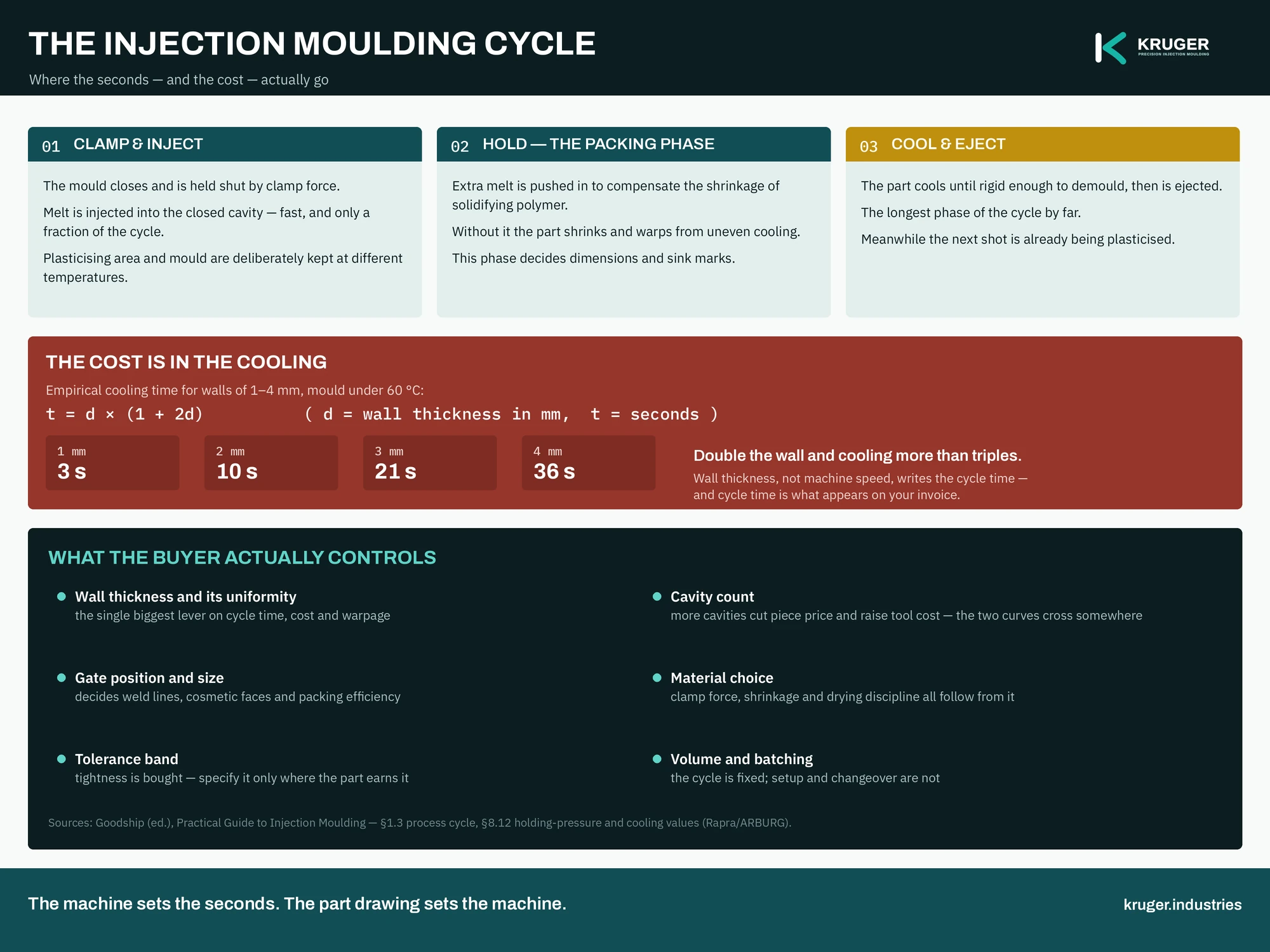
The part now sits in the mould losing heat until it is rigid enough to be pushed out without distorting. This is the longest phase of the cycle, and it obeys arithmetic rather than opinion. For parts of ordinary wall thickness — 1 mm to 4 mm, in a mould held below 60 °C — the process literature gives an empirical cooling time (Goodship, §8.12):
t = d × (1 + 2d) where d is wall thickness in millimetres and t is cooling time in seconds. Above a 60 °C mould temperature, add about 30 per cent.
| Wall thickness | Cooling time |
|---|---|
| 1 mm | 3 seconds |
| 2 mm | 10 seconds |
| 3 mm | 21 seconds |
| 4 mm | 36 seconds |
Read that table twice, because it is the most commercially useful thing on this page. Doubling the wall from 2 mm to 4 mm more than triples the cooling time. Cooling dominates the cycle, the cycle sets the machine hours, and machine hours are most of your piece price. A designer who thickens a wall “to be safe” has just made every part more expensive, for the whole life of the tool. That is why we wrote a whole guide on wall thickness and a cycle-time estimator — the two together will tell you more about your part cost than any quotation.
5 · Eject — and the part that surprises people
The mould opens, ejector pins push the part clear, and the cycle restarts. Two design details decide whether this is uneventful: draft angle, so the part releases rather than scrapes (our draft-angle calculator gives the offsets), and ejector placement, so the pins push where the part can take it.
Here is the surprise: the cycle is not sequential. While one part is cooling in the mould, the screw is already melting and metering the material for the next shot (Goodship, §1.3.3.3). Plasticising is hidden inside the cooling time. That overlap is why cooling — not melting, not injecting — is the phase that sets the pace, and why a moulder who quotes you a cycle time is really quoting you a wall thickness.
Thermoplastics and thermosets are not the same process
Everything above describes thermoplastics, where the mould is kept cool so the part solidifies. Thermosetting plastics invert that logic: the mould is kept warm, because the material must crosslink — cure — inside it, and once cured it cannot be remelted. That single difference changes the machine, the mould temperatures and the recyclability of the scrap. It also means thermosets can only be run on screw machines: without a screw, dwell time is too long and the material risks crosslinking before it reaches the cavity. Which family your part belongs to is the first question in any material conversation — our materials guide covers thermoplastics, thermosets, blends, alloys and composites, and Kruger runs thermoplastics.
The six things you actually control
The machine sets the seconds, but the drawing sets the machine. In order of financial impact:
- Wall thickness and its uniformity — the biggest single lever on cycle time, cost and warpage.
- Cavity count — more cavities cut the piece price and raise the tool cost; the two curves cross somewhere, and that crossing point is calculable.
- Gate position and size — decides weld lines, which faces stay cosmetic, and how efficiently the part can be packed.
- Material choice — clamp force, shrinkage and drying discipline all follow from it.
- Tolerance band — tightness is bought; specify it only where the part earns it.
- Volume and batching — the cycle is fixed by physics; setup and changeover are not.
Design decisions taken in an afternoon are paid for on every shot for years. That is the honest case for spending an hour on design for mouldability before asking for a price — and for reading what the common defects actually tell you, because most of them are design and process symptoms rather than bad luck.
Send the drawing
Understanding the cycle is what lets you read a quotation properly — and ask the questions that separate a moulder who has thought about your part from one who has weighed it. Kruger moulds precision components in Bengaluru, India: nine machines from 60 to 1300 tonnes, ISO 9001:2015, parts from 10 g to 5.2 kg, with product and mould-flow design done before any steel is cut and tooling manufactured by proven partner toolrooms under our design authority and supervision. Send a part drawing and an engineer replies with design-for-manufacture feedback within 48 hours on working days — start here, or run your own numbers first in the engineering tools.