
/ KNOWLEDGE · WALL THICKNESS
Wall thickness — the millimetre that sets your part price
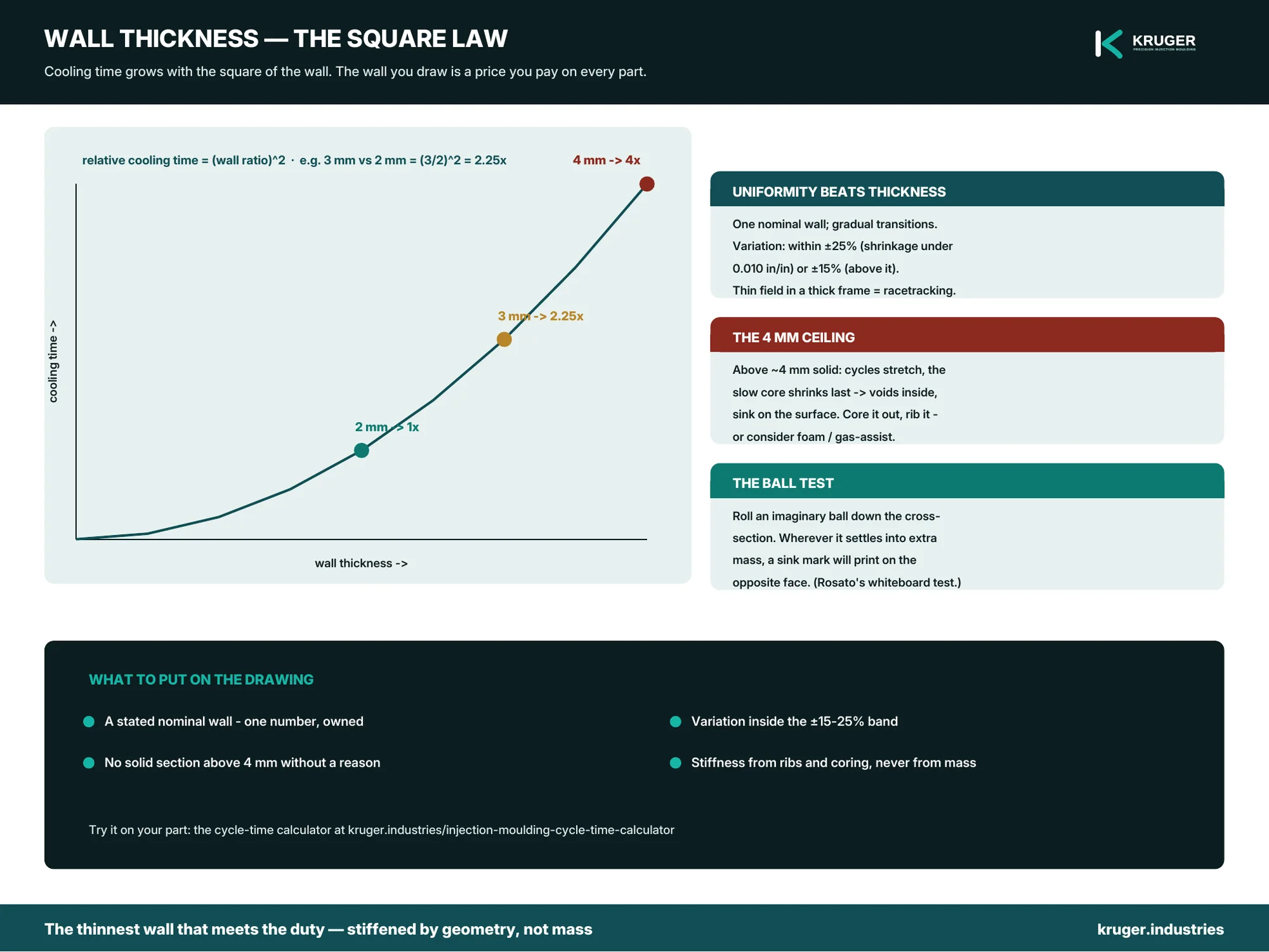
Cooling time grows with the square of wall thickness. That one sentence is most of injection-moulding economics: a part that could have been 2 mm but was drawn at 3 mm does not cool 50% slower — it cools roughly (3/2)², more than twice as slow. Cooling dominates the moulding cycle, the cycle sets the machine-hour share of your part price, and so the wall you choose on the drawing is a price you pay on every part, forever. This page is about choosing it deliberately.
The square law, and what it buys you
Heat leaves a moulded wall by conduction into the mould steel, and conduction through a slab takes time proportional to thickness squared — the basis of the handbook cooling-time relations and of our own cycle-time calculator, where you can watch the effect: enter your wall, then enter it 20% thinner, and compare the cycles. Working the law in your favour is the whole craft: the thinnest wall that meets the structural and flow requirement, stiffened by geometry rather than mass — ribs at half the wall, up to three times its height, per the design-for-mouldability rules.
Uniformity beats thickness
A moulded part shrinks as it cools; sections of different thickness shrink by different amounts at different times, and the part bends around the disagreement — warp. The handbook rules of thumb: keep the nominal wall as constant as possible; where transitions are needed, make them gradual; and hold variation within about ±25% for low-shrinkage materials (under 0.010 in/in) or ±15% for higher-shrinkage ones (Harper). Beware the frame-and-panel trap — a thin field inside a thick perimeter makes the melt race around the frame and trap gas in the panel (racetracking). And where the geometry seems to demand mass, core it out: a cored-out thick section cools like a thin one and keeps the structure.
The 4-millimetre ceiling
Above about 4 mm (0.150 in) of solid wall, the handbooks stop negotiating: cycles stretch badly, and the slow-cooling core shrinks after the skin has frozen, pulling voids inside the section or sink into the surface. If a design cannot come under the ceiling by coring and ribs, the honest answer may be a different process — structural foam and gas-assist exist precisely for thick-sectioned parts. A moulder who quotes a 6 mm solid wall without raising this conversation is quoting your money, not your part.
Reading sink before the tool exists
Sink marks print wherever local mass accumulates — under thick ribs, behind bosses, at wall junctions. Rosato’s crude-but-effective test needs no software: roll an imaginary ball down the part’s cross-section; wherever the ball settles into a pocket of extra material, a sink mark will appear on the opposite surface. (Mould-flow analysis will tell you the same thing with more decimals — we run it on request — but the ball finds most of them at the whiteboard.)
What to put on the drawing
- A stated nominal wall — one number, owned, not an accident of CAD filleting.
- Variation within the ±15–25% band for your material’s shrinkage class.
- No solid section above 4 mm without a note explaining why.
- Ribs and coring where stiffness is needed — geometry before mass.
Not sure what your part’s wall should be?
Send the drawing with the duty — loads, temperature, environment — and our DFM reply will state the wall we would mould, and what it does to your cycle and cost. Request a quote.