
/ KNOWLEDGE · DESIGN
Sink marks in injection moulded parts — a buyer’s guide
A sink mark is a shallow dip in the surface, usually over a rib, boss or thick section, and it is the defect most often argued over between buyer and moulder. The argument is easier to settle once both sides agree it can have a design cause, a process cause, or both. Harper explains the mechanism: the molten core of a thick wall shrinks more than the skin that has already set, and the core pulls the surface in. This page covers the three process causes, the design rules that prevent most sinks, a trap that can hide a worse defect, and five questions for any moulder. See also our guide to moulding defects.
Three process causes
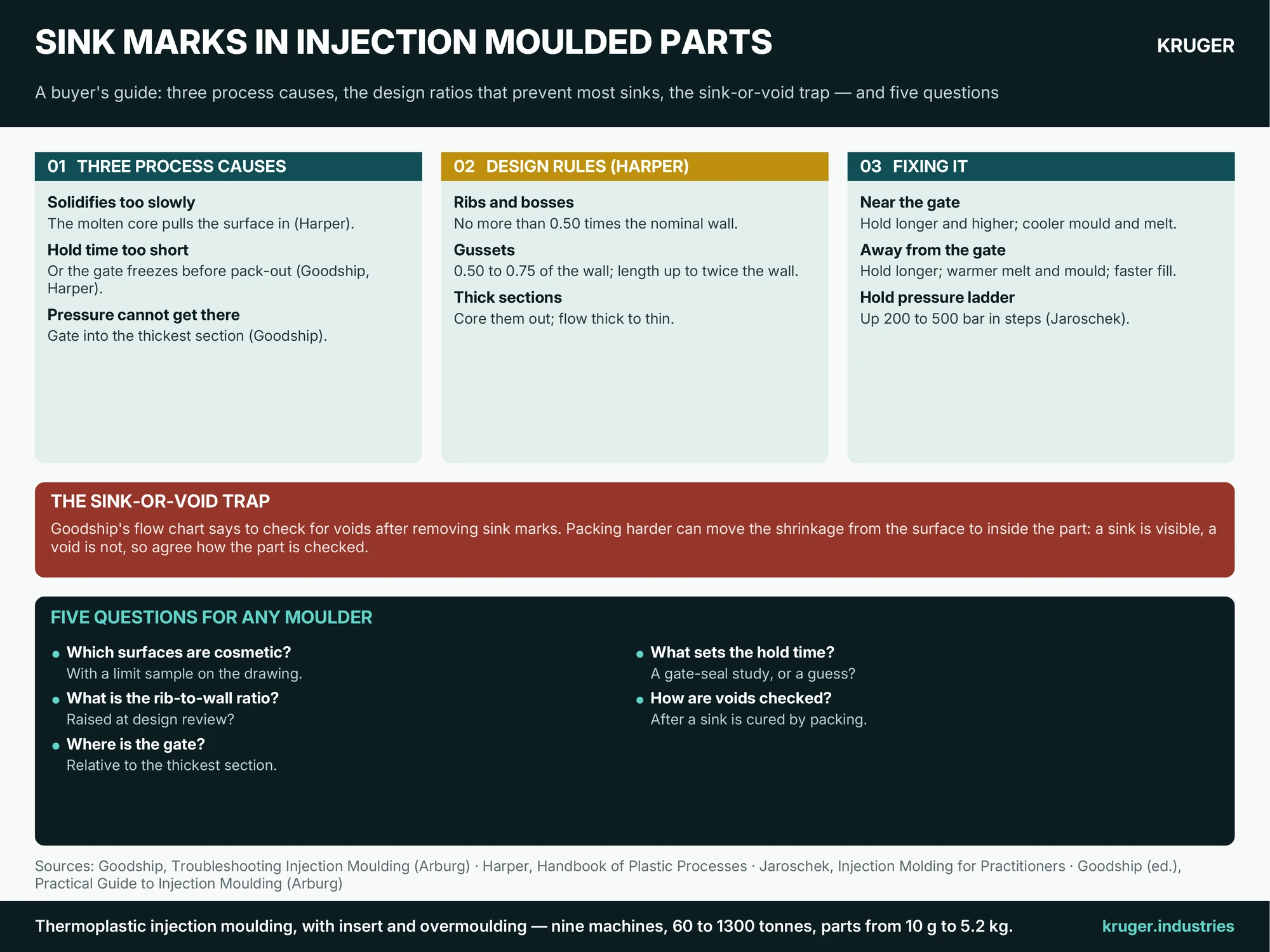
Goodship’s troubleshooting guide names three fundamental cases: solidification is too slow, the effective holding-pressure time is too short, or not enough holding pressure reaches the part because flow resistance in the mould is too high. For best pressure transfer she says the part should be gated into its largest cross-section. Goodship also notes that if the outer walls are not stable enough because of insufficient cooling, the outer layer is drawn inward by cooling stresses. Harper adds the supporting causes: too short a cooling time, a gate that freezes before the cavity is packed, a runner so small that it freezes early, a worn check ring that packs shots inconsistently, and a mould so cold that the skin sets well ahead of the core. Arburg gives a concrete example for polyethylene: if the hold time ends before the gate freezes, the high shrinkage leaves sink marks or cavities.
The sink-or-void trap
Goodship’s flow chart carries a warning in its footnote: check whether there are voids in the part after the sink marks have been removed. Packing harder can pull the dip off the surface and leave the shrinkage as an internal cavity instead. A sink is at least visible; a void is not. So a sink-mark complaint that is “fixed” by the moulder should be followed by a sectioned part, or another agreed check, rather than by a glance at the surface.
How the books sort the fixes
Goodship’s chart separates the cases by where the sink sits, with a plus or minus beside each setting. Sinks near the gate or in thick walls call for longer or higher holding pressure and lower mould wall temperature, melt temperature and injection rate. Sinks away from the gate or in thin areas call for the same hold changes but higher injection rate, melt temperature and mould temperature. If the sink appears directly after demoulding, she points to venting, sprue and gate dimensions, granule condition, mould temperature control, material accumulations, the wall-to-rib ratio, a blowing agent, or a low-shrinkage plastic. She also asks for a residual melt cushion of at least 2 to 5 mm. Jaroschek gives the operator’s ladder for sinks near the sprue: raise holding pressure by 200 bar for small sinks and up to 500 bar for large ones, then reduce injection speed, then melt temperature. Our guide to scientific moulding explains how to set the hold time with evidence.
Design rules that prevent most sinks
- Ribs and bosses. Harper recommends rib and boss thickness of no more than 0.50 times the nominal wall, and keeping the intersection of a projection with the wall at no more than 50% of the nominal wall thickness.
- Gussets. Gusset rib thickness between 0.50 and 0.75 times the nominal wall, and length of the reinforcing rib not above twice the wall (Harper).
- Core out thick sections, and direct the flow from thick to thin rather than thin to thick (Harper).
- Cool the problem spot. Harper suggests bubblers, cooling pins or metal inserts, and lowering mould temperature on the side where the sink shows. Jaroschek’s glossary names the rib foot as the classic place for a visible sink.
These ratios belong in the design review; see our guides to wall thickness and design for mouldability, and to mould cooling. The sister defect is covered in our warpage guide.
Five questions for any moulder
- Which surfaces are cosmetic? Agree them on the drawing, with a limit sample for acceptable sink.
- What is the rib-to-wall ratio behind each visible rib or boss, and was it raised at design review?
- Where is the gate relative to the thickest section?
- What evidence sets the hold time: a gate-seal study, or a guess?
- After a sink is cured by packing harder, how is the part checked for voids?
Send the part drawing and mark the surfaces that matter, and we will go through these questions with you.