
/ KNOWLEDGE · TOOLING
Mould cooling channels — what the water is doing and how to judge a layout
The cooling time a moulder quotes is only as good as the water circuits that deliver it. The same part moulded in two tools with the same steel and the same machine can warp in one and not the other, because the water reached different places at different speeds. Kulkarni calls the mould a heat transfer unit, whose job is to give consistency shot to shot, run to run and cavity to cavity. This page covers how many channels are enough, why the flow must be turbulent, what the coolant is, series versus parallel circuits, hard-to-cool areas, and five questions for any moulder. For the time itself, see our cooling time guide.
How many channels, and where
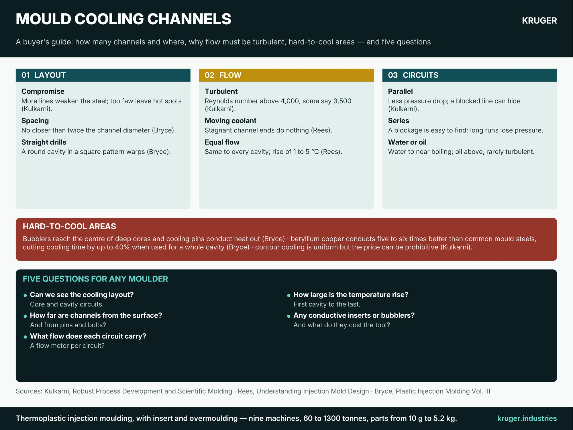
Kulkarni says the ideal is a constant steel temperature at every point in the cavity, which would need coolant enveloping it. Real tools compromise: more lines around the part risk weakening the cavity steel against injection pressure, and ejector pins and core pins compete for the same space, while too few lines leave hot and cold spots and let the tool temperature drift. There is no easy formula, he adds, because every part differs; software helps, and contour cooling, with channels machined to follow the part surface, gives uniform cooling but the price can become prohibitive. Bryce gives a rule of thumb that channels should sit no closer than twice their diameter from any other object, to leave enough steel around them. He also warns that drilled lines run straight while parts are three-dimensional: a round cavity surrounded by a square pattern of lines cools unevenly and tends to warp and bow.
Flow must be turbulent
Kulkarni explains why. In laminar flow the coolant moves in layers, the layer touching the steel warms, and heat transfer falls and varies, which changes part quality. In turbulent flow the coolant mixes and carries heat away steadily. A Reynolds number above 4,000 ensures turbulence, he says, though some texts accept about 3,500. If water still warms noticeably, the line diameter or the number of lines needs to increase, and a bigger line needs more flow. Rees’s rules point the same way: only moving coolant removes heat, so stagnant ends of channels do nothing; and every cavity and core should get the same flow, with the temperature rise between the first and last cavity of a group on the order of 1 to 5 °C.
Water, oil and the circuit
Water is inexpensive and reaches turbulence easily, but it is limited by its boiling point, so Kulkarni says oil is used for hotter moulds, where flow is rarely turbulent and heat transfer is harder. Long flow paths, including the hoses to the temperature unit, cost pressure and so flow. On circuits, parallel lines have less pressure drop and a higher velocity, but the coolant takes the path of least resistance, so a blocked line may starve without anyone noticing unless each line has its own flow meter. Series circuits make a blockage easy to locate with one flow meter but can lose too much pressure if too long. Kulkarni adds that if every part suddenly develops quality problems, a water line is a candidate. Scale and corrosion in service are covered in our mould maintenance guide.
Hard-to-cool areas
Bryce describes bubblers, where water rises through an inner tube and falls back around it, to reach the centre of a deep core, and cooling pins, which conduct heat from the plastic to the coolant. He reports that copper alloys such as beryllium copper conduct heat five to six times better than common mould steels, and that using them for an entire cavity can cut cooling time by up to 40%. They suit hard-to-cool areas and core pins. Aluminium is the other conductive option; our aluminium versus steel mould calculator compares the economics. Uneven cooling leaves its mark in warpage and in sink marks.
Five questions for any moulder
- Can we see the cooling layout at design review, with core and cavity circuits shown?
- How far are channels from the cavity surface and from pins and bolts, and which areas are hard to cool?
- What flow does each circuit carry, and is there a flow meter per circuit?
- How large is the coolant temperature rise from the first cavity to the last?
- Is any conductive insert, bubbler or cooling pin used, and what does it cost the tool?
Send the part drawing and tell us which areas have warped before, and we will go through these questions with you.