
/ KNOWLEDGE · MACHINES
Setting clamping force — why the books disagree, and how a good moulder settles it
The clamping force a part needs is not a figure you look up — it is a figure a moulder settles at the machine, and the published starting points differ more than most buyers expect. Clamp force exists to hold the mould shut against the pressure of the melt. The usual first estimate multiplies the part’s projected area — every cavity plus the runner — by a factor for the material, and our clamping-force calculator does that sum for budgeting. This page is about what the factor really stands for, why respected handbooks give different answers for the same polymer, and the questions that show whether a moulder sets tonnage by trial or by habit.
Same polymer, different books
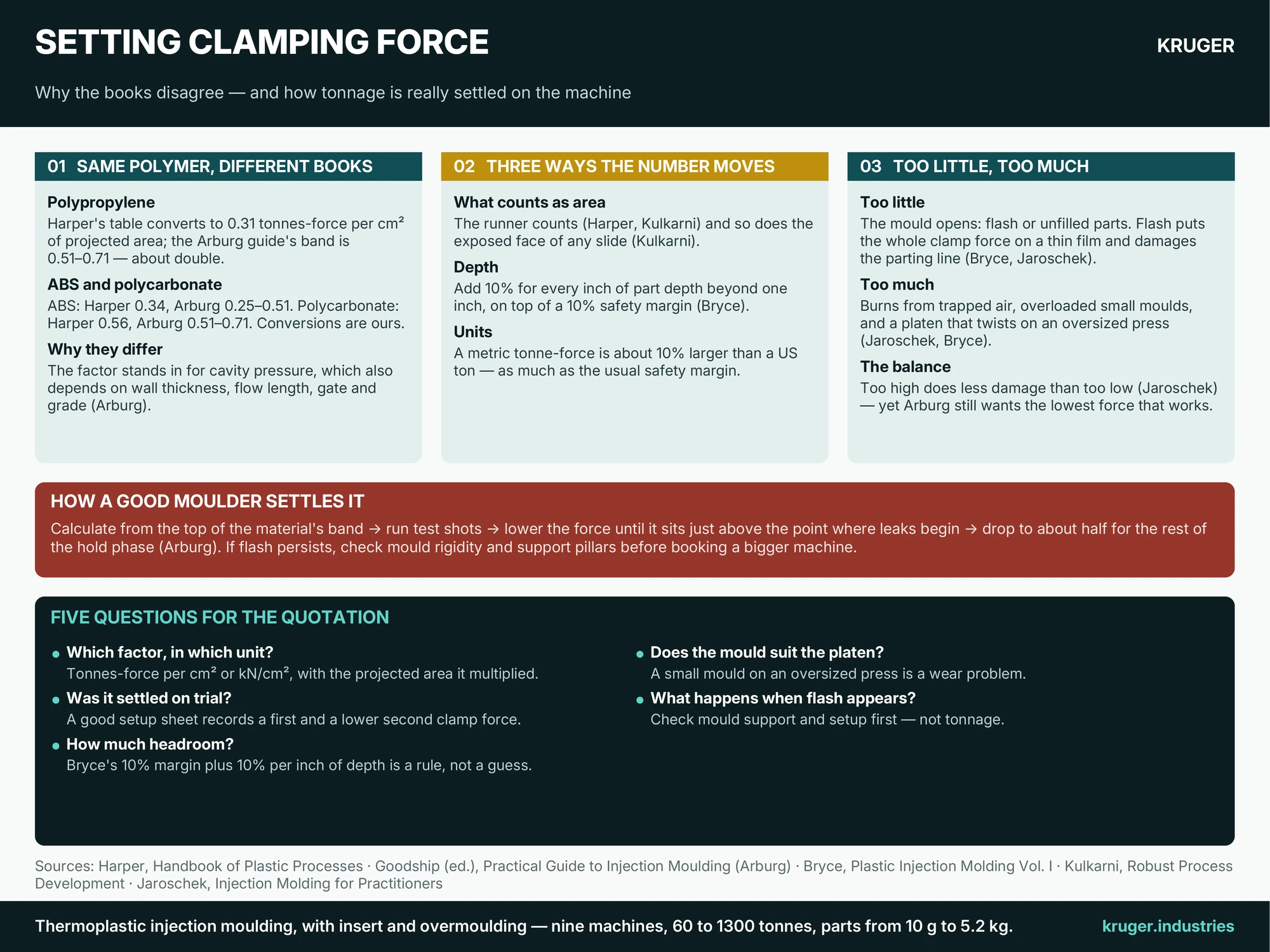
Harper’s handbook tabulates tonnage per square inch of projected area, polymer by polymer. The Arburg guide edited by Goodship gives two bands in kilonewtons per square centimetre. Bryce allows anything from 2 to 8 US tons per square inch and says to use 5 when in doubt; Kulkarni gives 3.5 to 4.5 for semi-crystalline materials and 2.5 to 4.0 for amorphous ones. Put into one unit — tonnes-force per cm², the unit of our calculator — the spread for a single polymer is wide.
| Polymer | Harper’s table | Arburg guide’s band |
|---|---|---|
| Polypropylene | 0.31 | 0.51–0.71 |
| ABS | 0.34 | 0.25–0.51 |
| Polycarbonate | 0.56 | 0.51–0.71 |
| Acetal (POM) | 0.70–0.98 | 0.51–0.71 |
Polypropylene is the sharpest case: Arburg’s band sits at roughly double Harper’s single figure. Neither author is careless. The factor is a stand-in for cavity pressure, and cavity pressure depends on wall thickness, flow length, gate position and grade as much as on the polymer family. Arburg states the underlying relationship directly — closing force equals cavities times projected area times cavity pressure, with the pressure rising as the flow path lengthens against the wall thickness. A thin-walled part therefore needs more than its table value.
Three ways the number moves
First, what counts as area: Harper and Kulkarni include the runner, and Kulkarni adds the exposed face of any slide, because melt pressure acts on it too. Second, depth: Bryce adds 10 per cent for every inch of part depth beyond one inch, on top of a 10 per cent safety margin. Third, units: Bryce’s “200 tons” is 1,780 kN, a US ton, whereas a metric tonne-force is about 10 per cent larger — and 10 per cent is the whole of the usual safety margin. Ask which ton a quotation means.
Too little, too much
Too little clamp lets the mould open under pressure, which Bryce says produces flash or unfilled parts. Jaroschek explains why even slight flash is costly: once it forms, the whole clamp force bears on the thin flash, the pressure on the parting line climbs sharply, and repeated shots crush the steel until the mould can no longer seal. Too much clamp is not free either. Jaroschek lists burns from trapped air and overloaded small moulds, and Bryce adds that a mould mounted on a platen far larger than it needs lets the moving platen twist and wear the machine. Jaroschek’s balance of the two: “too high a clamping force causes less damage than too low a clamping force.” Arburg still asks for the lowest force that works, which saves energy and wear and lets air leave the cavity.
How a good moulder settles it
Arburg’s start-up method is the model: calculate from the top of the band for the material, run test shots, then lower the force until it sits just above the point where leaks begin. When the hold phase is over the clamp can drop, to about half, for the rest of the hold — a second clamping force. Arburg also warns that flash is more often a mould-rigidity problem than a tonnage one: plates that bend around the ejector area need support pillars, not a bigger machine. Our guide to moulding defects develops that point, and the toggle clamp guide covers how clamp force is actually measured.
Five questions for the quotation
- Which factor, in which unit? Ask for tonnes-force per cm² or kN/cm², with the projected area it multiplied, runner and slides included.
- Was the number settled on trial? A good setup sheet records the first clamp force and the lower second one.
- How much headroom — and for a deep part? Bryce’s 10 per cent margin plus 10 per cent per inch of depth is a stated rule, not a guess.
- Does the mould suit the platen? A small mould on an oversized press is a wear problem, not extra safety.
- What happens when flash appears? The right first move is to check mould support and setup, not to book a bigger machine.
Our machine guide shows how clamp, shot and mould size fit together, and the injection pressure guide explains where the pressure behind these forces comes from. Send the drawing and an engineer will reply with a tonnage and the machine it would run on.
Sources quoted: V. Goodship (ed.), Practical Guide to Injection Moulding (Arburg / Rapra Technology, 2004); C. A. Harper (ed.), Handbook of Plastic Processes (Wiley, 2006); D. M. Bryce, Plastic Injection Molding, Vol. I (Society of Manufacturing Engineers, 1996); S. Kulkarni, Robust Process Development and Scientific Molding, 2nd ed. (Hanser, 2017); C. Jaroschek, Injection Molding for Practitioners (Hanser).