
/ KNOWLEDGE · DESIGN
Weld lines in injection moulding — strength, appearance and what to put on the drawing
A weld line, also called a knit line, is where two streams of melt meet inside the cavity and bond. Any part with a hole, a slot or more than one gate will have one. The useful questions are where it falls, how strong it is and how visible it is. Our guide to injection moulding gates shows how to count weld lines before the tool exists. This page covers what makes one weak, what improves it, what each remedy costs, and how a buyer can specify acceptance. Taken with the wider defects guide, it should help you judge any moulder’s answer.
How a weld line forms, and why it is weak
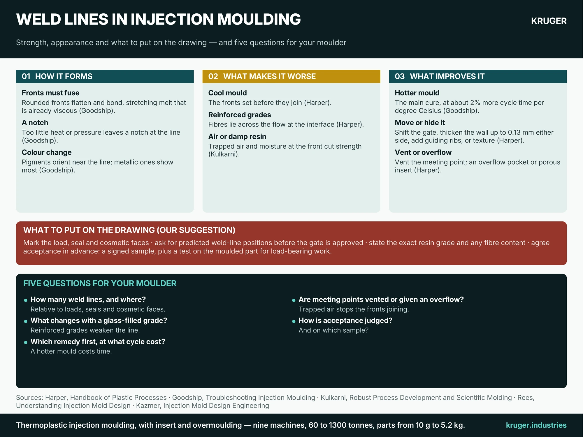
Goodship’s troubleshooting guide explains that the rounded flow fronts must be flattened and bonded, which means stretching fronts that are already highly viscous. If temperature and pressure are too low, the corners of the fronts do not fully develop and leave a notch. The fronts also no longer fuse evenly, so the line can be both an optical and a mechanical weak spot. Where the material carries pigment, the additives can orient near the line and change the colour, particularly with metallic pigments. Notches show most on dark or transparent parts with smooth, highly polished surfaces.
What makes it worse
- A cool mould. Harper notes that at low mould temperatures the fronts set before they join, giving weak and more pronounced lines.
- Stiff-flowing or reinforced grades. Easy-flowing, low-viscosity resins give less noticeable lines with higher strength. Filled and reinforced grades give weaker ones, partly because fibres lie across the flow at the interface (Harper). Goodship’s photographs show glass-fibre streaks making a weld line clearly visible. Our polymer composites guide explains these grades.
- Long flow paths. Harper cites melt running a long way round a core, as in a television housing or bezel.
- Race-tracking. Kazmer’s container example shows melt racing round the side walls when the part is deep relative to its width, meeting opposite the gate to form a weld line and a gas trap.
- Trapped air. If air cannot escape where the fronts meet, they cannot come together. Kulkarni links plugged vents to lost weld strength, and Rees advises locating vents at the expected meeting points.
- Damp resin. Kulkarni reports that moisture at the flow front stops the weld developing its full strength. See our guide to drying plastics.
What improves it, and what it costs
Goodship says significant improvement comes only from a hotter mould wall, and puts the price at roughly 2% more cycle time per degree Celsius. On that figure, ten degrees hotter means a cycle about a fifth longer, which a buyer will see in the piece price. Goodship’s flow chart also lists a faster injection rate and a moved gate.
Harper adds design remedies. Thickening the wall by no more than about 0.13 mm (0.005 in) either side of the line can shift it away from a critical area, as can moving the gate or adding ribs that guide the flow. A textured finish can hide a line (see our surface finish guide). At the meeting point, an overflow pocket lets the cold front run out of the part so the fresh melt bonds, but the pocket usually has to be removed by hand. A porous-metal insert can draw off trapped gas; Harper recommends it mainly for textured surfaces, since a smooth surface may show a slight gloss difference.
What to put on the drawing
These four steps are our suggestion, not a book rule. First, mark the faces that carry load, seal or must look perfect, so nobody guesses where a line may not fall. Second, ask to see the predicted weld-line positions before the gate is approved, because moving the gate is the cheapest cure. Third, state the exact resin grade and any fibre content in the request for quotation, since it changes the answer. Fourth, agree acceptance in advance: a signed appearance sample, and for a load-bearing part a functional test on the moulded part itself.
Five questions for your moulder
- How many weld lines will this part have, and where do they fall relative to loads, seals and cosmetic faces?
- What changes if we move to a glass-filled grade?
- Which remedy will you try first, and what does each cost in cycle time?
- Are the meeting points vented, or given an overflow?
- How will weld-line acceptance be judged, and on which sample?
Send the part drawing and we will go through these questions with you before any tooling decision is made.