
/ KNOWLEDGE · DESIGN
Custom Plastic Enclosure for a PCB: Catalogue Box or Tool?
A custom plastic enclosure for electronics is a purchase of two things: a tool, paid once, and a housing that then arrives with every standoff, opening and clip already in it. A catalogue box costs nothing up front and something on every unit, because each is machined and fitted out before the board goes in. Ratings, sealing and terminal inserts are in our enclosure specification guide; what we mould for the sector is on our electrical enclosures page.
Catalogue box or tool: where the lines cross
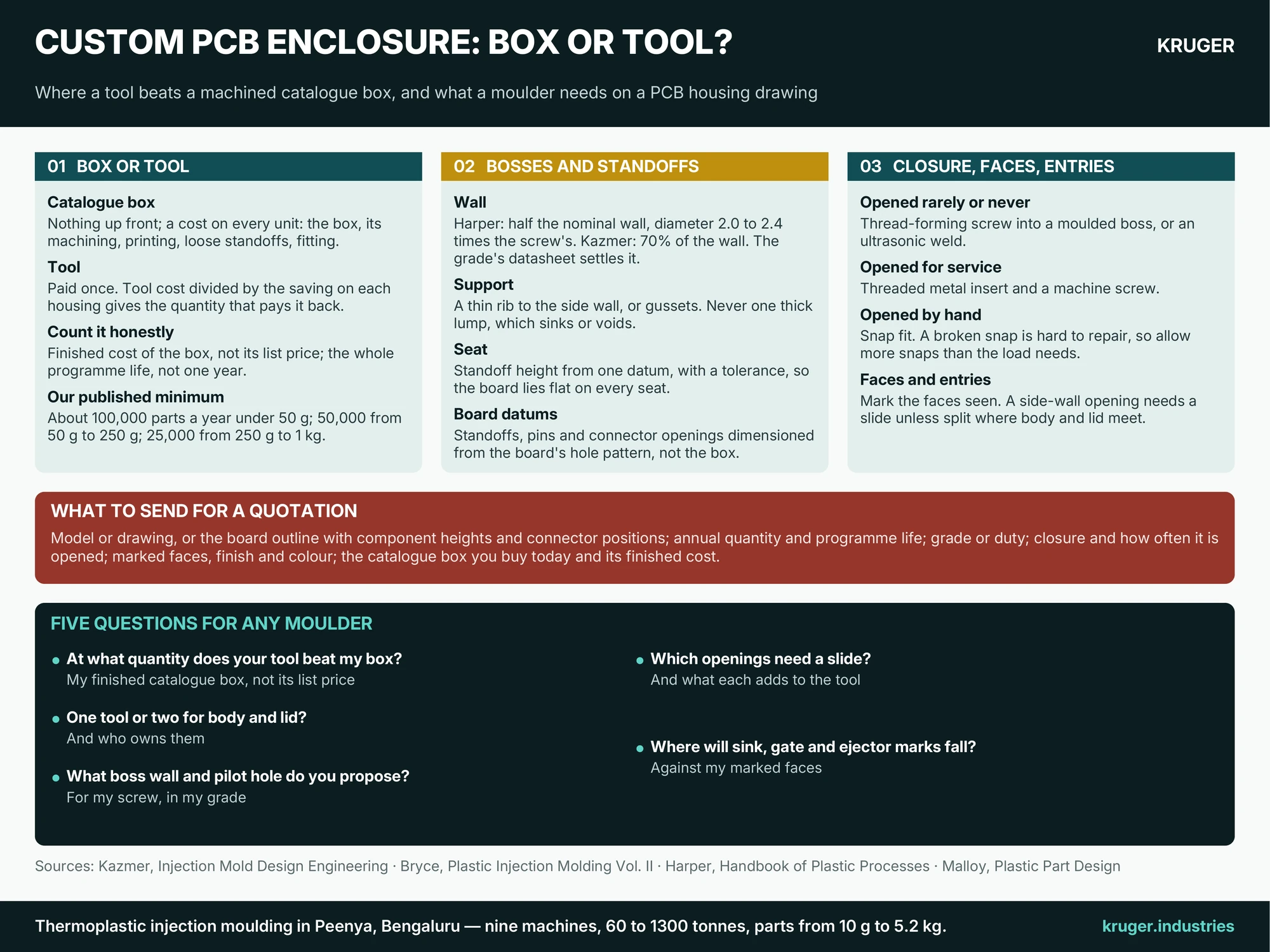
Kazmer’s mould-design text sets the comparison out as a fixed cost plus a cost per piece multiplied by the quantity, and finds the break-even by setting two such totals equal. The catalogue route has no fixed cost and a high cost per piece: the box, its machining, the printing, the loose standoffs and the labour to fit them. Divide the tool cost by what you save on each housing and you have the quantity at which the tool has paid for itself. Use the finished cost of the catalogue box, not its list price, and the whole programme life, not one year.
A housing is usually a body and a lid, so two tools or one tool carrying both; the indicative bands are on our mould cost page. And every moulder has a floor. Our published minimum is about 100,000 parts a year under 50 g, 50,000 from 50 g to 250 g and 25,000 from 250 g to 1 kg. Below it, a catalogue box, or a smaller shop with a simpler tool, is the honest answer, and we say so.
What a custom plastic enclosure for electronics buys besides price
Bryce’s product-design volume gives the reason for moulding at all: bosses, holes, attachment points and snap fittings designed into the part remove the operations that would follow. In a PCB housing that means standoffs at your hole pattern, openings where your connectors sit and a closure with no loose hardware. If your catalogue box needs none of that work, keep buying it.
Bosses and standoffs for the board
A boss is a hollow post that takes a screw; a standoff is a boss whose top seats the board.
- Its wall. Harper’s handbook puts the boss wall at half the nominal wall, to keep a sink mark off the outside face, and the boss diameter at 2.0 to 2.4 times the screw’s. Kazmer draws his bosses at 70 per cent of the wall. So name the resin grade and let its maker’s datasheet settle the figure.
- Its support. A post standing alone is weak in twisting. Tie it to the side wall with a thin rib or brace it with gussets; never merge it into the wall as a thick lump, which sinks or voids.
- Its seat. Bryce’s rule for a self-tapping screw is that the fastened part sits flush on the top of the boss. Give the standoff height from one datum, with a tolerance, so the board lies flat on every seat.
Screw, insert or snap: how the lid closes
One question decides the closure: how often will the housing be opened?
- Rarely or never. A thread-forming screw driven straight into a moulded boss. Harper names a cracked boss as its commonest fault, cured by a larger boss, a larger hole or a smaller screw. A housing that is never opened can be ultrasonically welded.
- For service. A threaded metal insert and a machine screw. Moulded in, the insert is strongest and adds cycle time and cost; fitted into a cored hole after moulding is the other route.
- By hand. A snap fit formed in the tool, with no fastener. Malloy’s caution is that a broken snap is hard or impossible to repair and can scrap the housing, so he suggests more snaps than the load needs. Geometry is in our snap fits guide.
Board tolerances and datums
The board does not shrink; the housing does. Dimension the standoffs, the locating pins and the connector openings from the board’s own hole pattern, not from the outside of the box. Give the board outline and thickness with their tolerances, the tallest component on each side and the clearance needed under the lid. Say which openings must line up with a connector. Those few carry the tight tolerances; the rest stay general.
Cosmetic faces and entries
Mark the faces a customer sees. Sink shows where a boss or rib meets the wall, so the gate, the ejector pins and the heaviest features belong behind the faces you did not mark. Show every entry: connector and cable openings, display window, light pipes, vents. An opening in a side wall needs a slide in the tool unless it is split across the line where body and lid meet, and every slide is tool money.
What to send for a quotation
- The model or drawing. If the housing is not designed yet, the board outline with component heights and connector positions.
- Annual quantity and programme life.
- Material grade, or the duty: indoors or outdoors, temperature, flammability class.
- The closure, and how often the housing is opened.
- Marked faces, finish and colour.
- The catalogue box you buy today, and its finished cost.
Five questions for any moulder
- At what quantity does your tool beat my finished catalogue box?
- One tool or two for body and lid, and who owns them?
- What boss wall and pilot hole do you propose for my screw in my grade?
- Which openings need a slide, and what does each add to the tool?
- Where will sink, gate and ejector marks fall against my marked faces?
Send the list above through our RFQ page, or contact us first with a question. Madhusudhan, our Head of Production, replies with DFM feedback within 48 hours on working days. The tool is built by a partner toolroom under our design authority and stays your property. If a catalogue box is the better buy at your volume, the reply says so.
Sources quoted: D. O. Kazmer, Injection Mold Design Engineering (Hanser, 2007); D. M. Bryce, Plastic Injection Molding, Vol. II: Material Selection and Product Design Fundamentals (Society of Manufacturing Engineers, 1997); C. A. Harper (ed.), Handbook of Plastic Processes (Wiley, 2006); R. A. Malloy, Plastic Part Design for Injection Molding (Hanser, 1994).