
/ KNOWLEDGE · DESIGN
Undercuts in injection moulding — how moulds form them, and when to design them out
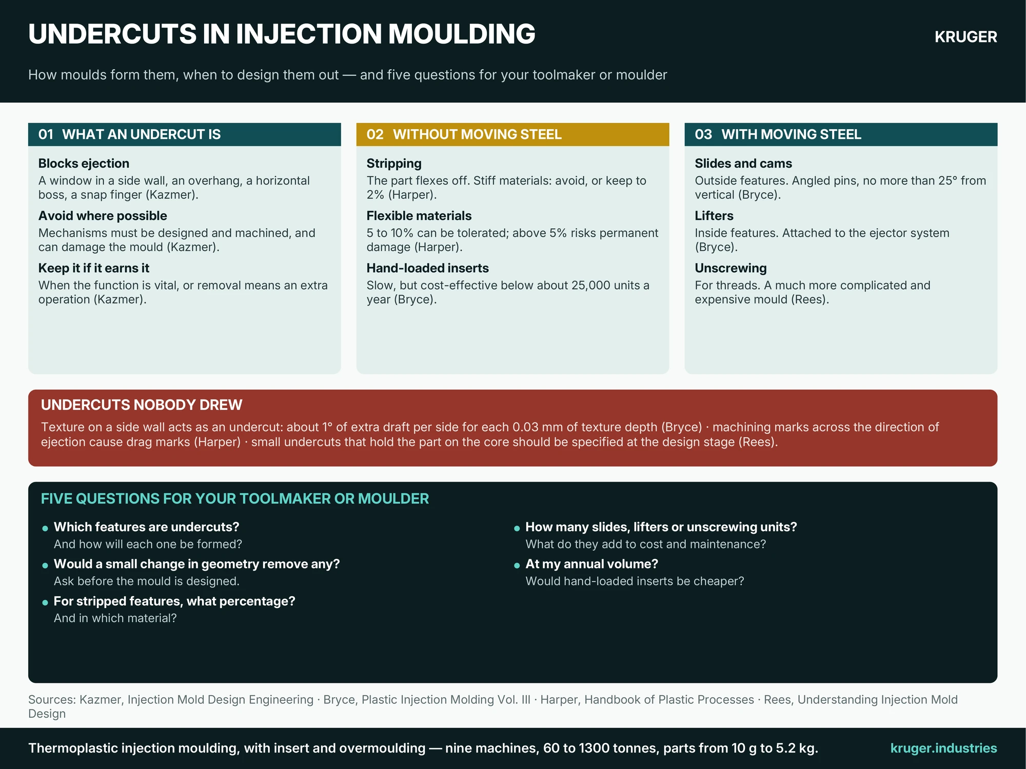
An undercut is any feature that stops a part coming straight out of the mould. Kazmer gives four common examples: a window in a side wall, an overhang above the base, a horizontal boss and a snap finger. He adds that the product designer is often unaware of the difficulty. Each undercut needs either a part that can flex off the steel or a piece of steel that moves out of the way, and moving steel is a machine built inside the mould. This page explains the five ways a mould deals with an undercut and the questions to ask before you approve one. It builds on our guides to design for mouldability and mould cost.
Why the buyer should care
Kazmer’s advice is to avoid undercuts where possible, because the mechanisms they need must be designed and machined, make the mould harder to use, and can damage it if used wrongly. He also describes a conflict of interest plainly: a mould designer may see that a slight change of angle would remove an undercut, yet stay silent because the core pull justifies a dearer mould. So ask. The reverse also holds. Kazmer says an undercut should stay if its function is vital, or if removing it would mean an extra operation after moulding or splitting one part into several.
Five ways a mould handles an undercut
- Stripping. The part flexes over the steel as it is pushed off. Kazmer’s test is whether the strain stays within the material’s elastic limit, and he calls stripper plates ideal for the job. Harper measures the undercut as a percentage of the diameter it must stretch over. For stiff materials such as polycarbonate, ABS and filled nylons he advises avoiding it, or keeping to 2% with flexible, bevelled walls. For flexible ones such as unfilled nylon 6, polypropylene and polyethylene, 5 to 10% can be tolerated, though above 5% risks permanent damage. The feature must also sit away from stiffening corners and ribs.
- Slides and cams. For features on the outside of the part. Bryce’s examples are a thread, a side wall with no draft, and a large window in the side of a box. A slide moves a whole section of the cavity; a cam moves one small feature such as a hole. Most are driven by angled pins set no more than 25° from vertical, with stops and switches to keep the slide in position, because a slide out of place when the mould closes causes serious damage. Our guide to mould types shows where these sit.
- Lifters. For features on the inside. A lifter is attached to the ejector system and travels up with the part as it moves sideways (Bryce).
- Unscrewing. For threads. Either the threaded steel rotates out of the part or the part is rotated off. Rees calls this a much more complicated and expensive mould. He notes that an internal thread designed for it can instead be stripped, preferably with no more than one complete turn. Harper adds that moulded thread roots should be radiused and extra-fine threads avoided.
- Hand-loaded inserts. A loose piece of steel is placed in the mould each cycle, ejected with the part and removed by hand. It is slow, but Bryce rates it more cost-effective than mechanical unscrewing below about 25,000 units a year.
Snap rims: the undercut you asked for
A snap rim inside a cap is an undercut by design. Rees explains that a suitably tapered or rounded rim strips off without trouble, and that a rim can be broken into, say, four sections so that it stretches more easily, with the customer’s approval. Larger internal snaps may need two-stage ejection, which he describes as a dearer core and mechanism. Our guide to snap fits and living hinges covers the joint itself.
Undercuts nobody drew
Some undercuts are accidental. Bryce points out that texture on a side wall acts as an undercut and needs about 1° of extra draft per side for each 0.03 mm of texture depth; see our surface finish guide and the draft-angle calculator. Harper notes that machining marks running across the direction of ejection behave the same way and cause drag marks. Others are deliberate but small: Rees describes slight undercuts placed on the core to hold the part on the correct half as the mould opens, and says they should be specified at the design stage, not added after ejection trouble starts.
Five questions for your toolmaker or moulder
- Which features on my part are undercuts, and how will each one be formed?
- Would a small change in geometry remove any of them?
- For anything stripped off the core, what is the undercut percentage, and in which material?
- How many slides, lifters or unscrewing units are there, and what do they add to mould cost and maintenance?
- At my annual volume, would hand-loaded inserts be cheaper than a mechanism?
Send the part drawing and we will go through these questions with you before any tooling decision is made.