
/ KNOWLEDGE · TOOLING
Types of mould in injection moulding — two-plate, three-plate, hot runner and the rest
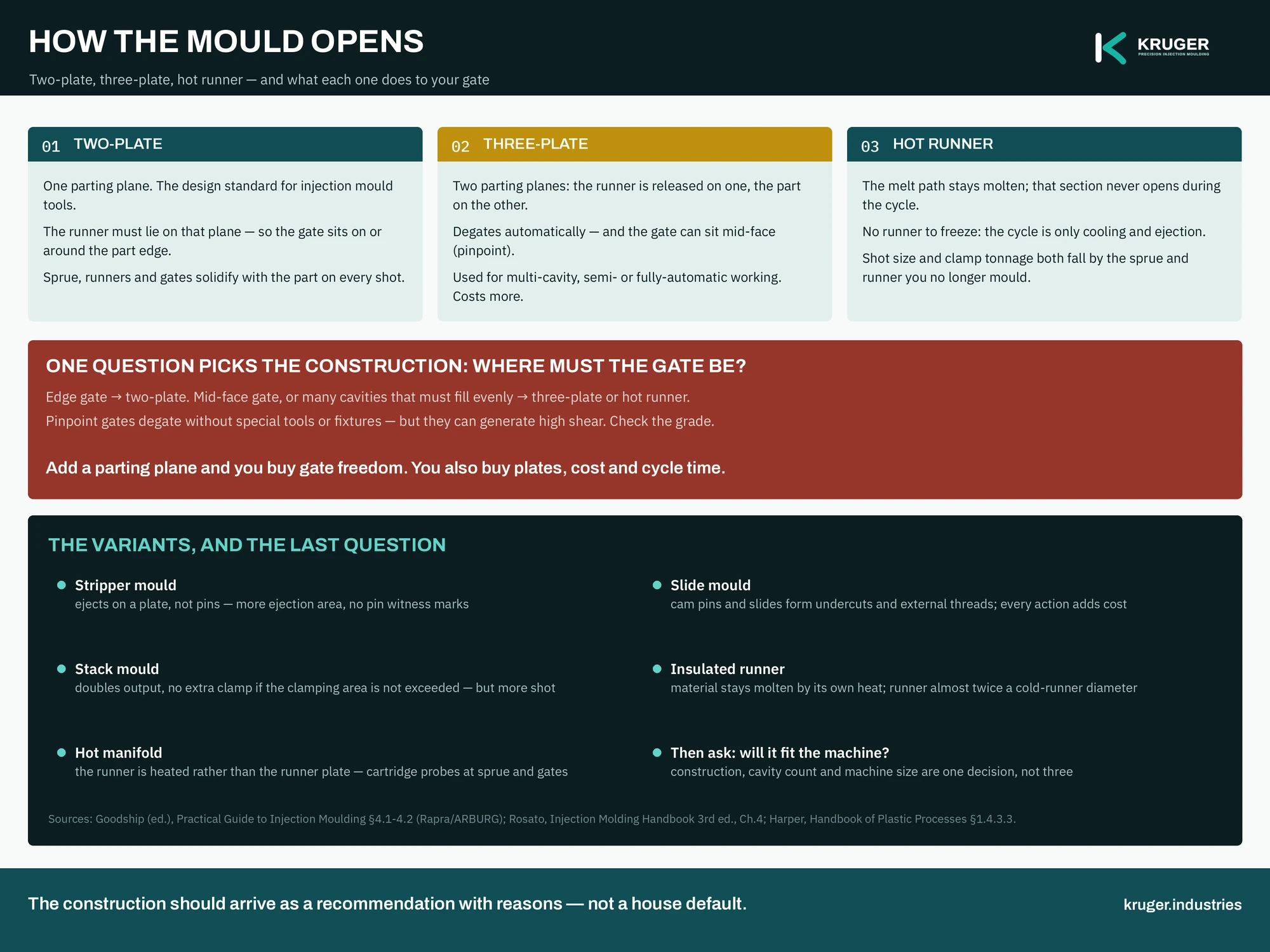
Moulds are classified by how they open. The process literature groups the moulds used for thermoplastics into six basic types: the cold-runner two-plate mould, the cold-runner three-plate mould, the hot-runner mould, the insulated hot-runner mould, the hot-manifold mould and the stacked mould (Rosato). That one choice — how many parting planes the tool has, and what happens to the runner when it opens — decides where your part can be gated, whether the runner comes off by itself, how much scrap you make every cycle, and a large share of what the tool costs. Here is how to read the choice on a quote.
The parting plane is the whole idea
A mould is two halves that meet on a parting plane. The stationary half bolts to the fixed platen; the moving half bolts to the moving platen and carries the ejection mechanism (Arburg). Everything the tool must do — fill, pack, cool, release the runner, eject the part — has to happen across those planes when the machine opens. Add a plane and you buy freedom. You also buy plates, movement, cost and cycle time. That is the entire trade, and every mould type below is one position on it.
Two-plate — the design standard
“The design standard for injection mould tools is the two-plate design” (Arburg §4.1). One parting plane. The cavities are formed in one plate with the stationary half of the mould blank; a central sprue bushing sits in the stationary half, or a runner feeds a multi-impression layout directly; the moving half contains the ejection mechanism.
The consequence for your drawing is simple, and often discovered late: the runner system has to lie on that single parting plane, so the gate must be on or around the edge of the part. Rosato calls the two-plate “the most logical type of tool to use for parts that require large gates”, and states the cold-runner price plainly — the sprue, runners and gates solidify along with the cavity material on every shot. That solidified runner is then regrind, sold scrap, or an argument: settle it in the order, not afterwards, with our guide to regrind policy.
If your part tolerates an edge gate, the conversation can stop here. A two-plate tool is cheaper to cut, simpler to maintain, and much faster to put right when something goes wrong at three in the morning.
Three-plate — what you are buying is gate freedom
A three-plate mould has, as the name says, an extra plate: the stationary or runner plate, which carries the sprue and half the runner; the middle or cavity plate, which carries the other half of the runner and the gate and is allowed to float when the mould is open; and the moving or force plate, which holds the moulded part and the ejection system (Rosato). Two parting planes. When the machine opens, the middle and moving plates travel together, releasing the sprue-and-runner system and degating the part in the same movement.
Arburg describes the same tool from the shop floor: three-plate moulds are normally used when multi-cavities are involved and semi- or fully-automatic working is required; a delayed-action mechanism — chains, or length bolts — separates the plates and breaks the restricted gate, and the mouldings are ejected from one daylight while the sprue and runner are ejected from the other.
What that buys is gate position. The gate can sit in the middle of a face instead of at the edge — pinpoint gating, which Harper notes is used mostly in single- or multi-cavity three-plate tools, with the practical advantage of degating without special tools or fixtures. Harper also gives the caution: pinpoint gates can generate high shear in the melt, so follow the material maker’s recommendation, and put your own numbers through our gate shear-rate calculator before the gate size is frozen.
What it costs is stated just as plainly: “Multi-plate moulds are usually more expensive than two-plate moulds and can be slower in production if an operator has to remove the sprue and runner system when the mould is open” (Arburg) — slower, that is, unless automatic ejection of sprue and runner is designed in. The cost side of that sentence belongs to the mould cost guide.
Runnerless — hot runner, insulated runner, hot manifold
In a hot-runner mould the melt path is kept molten between shots. The runner is contained in a plate of its own, and that section of the mould is not opened during the moulding cycle (Rosato) — which is why the family is sometimes called runnerless moulding. Two consequences matter to a buyer. The cycle is only as long as the part needs to cool and eject, because there is no runner to freeze and remove. And both the shot size and the clamp tonnage the machine must provide fall by the size of the sprue and runner you are no longer moulding.
Two relatives are worth recognising on a drawing. In the insulated-runner mould the material stays molten by retaining its own heat; it suits multi-cavity centre-gated parts, and its runner diameter is almost twice that of a cold-runner system. In the hot-manifold mould the runner itself is heated rather than the runner plate, using electric cartridge probes at the sprue, runners and gates (Rosato).
The economics of hot runner versus cold, the extra maintenance surface and the controller that comes with it are covered in the tooling guide; the colour-change penalty — a hot runner is slow to purge — is covered in colour in injection moulding. This page is about construction, so it stops at what the plates do.
Three variants that each solve one problem
- Stripper mould. A two-plate mould that ejects with a stripper plate instead of pins or sleeves; the advantage is the increased surface area for ejection (Arburg §4.1.2). The reason to ask for one is a thin-walled or deep part that pins would distort, or a cosmetic face you do not want witness marks on.
- Slide mould. Still a two-plate mould, but with slides and cam pins giving lateral movement — the standard way to form undercuts or external threads (Arburg §4.1.3). Every action adds tool cost, a moving surface to maintain and a witness line to agree in advance. Removing an undercut at the design stage is nearly always cheaper than building a slide to make it.
- Stack mould. A multiple two-plate mould with moulds placed one above the other. It doubles output from a single machine and — the part that surprises people — requires no more clamping force if a duplicate set of cavities is used, or if the maximum clamping cross-sectional area is not exceeded. The machine does, however, need additional shot capacity (Rosato). The construction can also be applied to three-plate, hot-runner and insulated hot-runner moulds.
Four questions that choose the construction
- Where must the gate be? An edge gate is a two-plate answer. A gate in the middle of a face, or many cavities that must fill evenly, is a three-plate or hot-runner answer.
- Must the runner come off by itself? Unattended running is an engineering requirement, not a preference — say it out loud, because it changes the tool.
- What happens to the runner afterwards? Reground, sold, or eliminated. Whichever it is, it belongs in the purchase order.
- Will the tool fit the machine that will run it? Construction, cavity count and machine size are one decision taken together, not three taken in sequence — our guide to how many cavities shows the two curves that cross.
How we handle it
Kruger designs the part and the mould, runs mould-flow analysis before any steel is cut, and commissions and manages tool manufacture with specialist toolmakers. That means the construction arrives as a recommendation with reasons attached — this many plates, this gate position, this runner decision, and what each one does to your piece price — rather than as a house default. Nine injection moulding machines from 60 to 1300 tonnes in Bengaluru, ISO 9001:2015, parts from 10 g to 5.2 kg; the moulding cycle and the engineering calculators let you check the arithmetic yourself.
Send the drawing and the annual volume. An engineer replies within 48 hours on working days with the construction we would recommend, the gate position it implies, and what it does to the cost of the tool and the cost of the part. If a simpler tool will do the job, that is the answer you will get.
Sources quoted: V. Goodship (ed.), Practical Guide to Injection Moulding (Arburg / Rapra Technology, 2004); D. V. Rosato, D. V. Rosato and M. G. Rosato, Injection Molding Handbook, 3rd ed. (Kluwer Academic, 2000).