
/ KNOWLEDGE · DESIGN
Warpage in injection moulded parts — where it comes from, and the fixes that actually work
Warpage is not one defect — it is unequal shrinkage, made visible. Injection moulding warpage — a part that comes off the mould twisted, bowed or saddle-shaped — is reporting a temperature or pressure difference that existed somewhere in the tool, not presenting a mystery. Our design for mouldability guide sets the rules that prevent most of it before the tool is cut; this page is for the sample that has already warped, and the arithmetic that says which gradient did it.
Three gradients, one mechanism
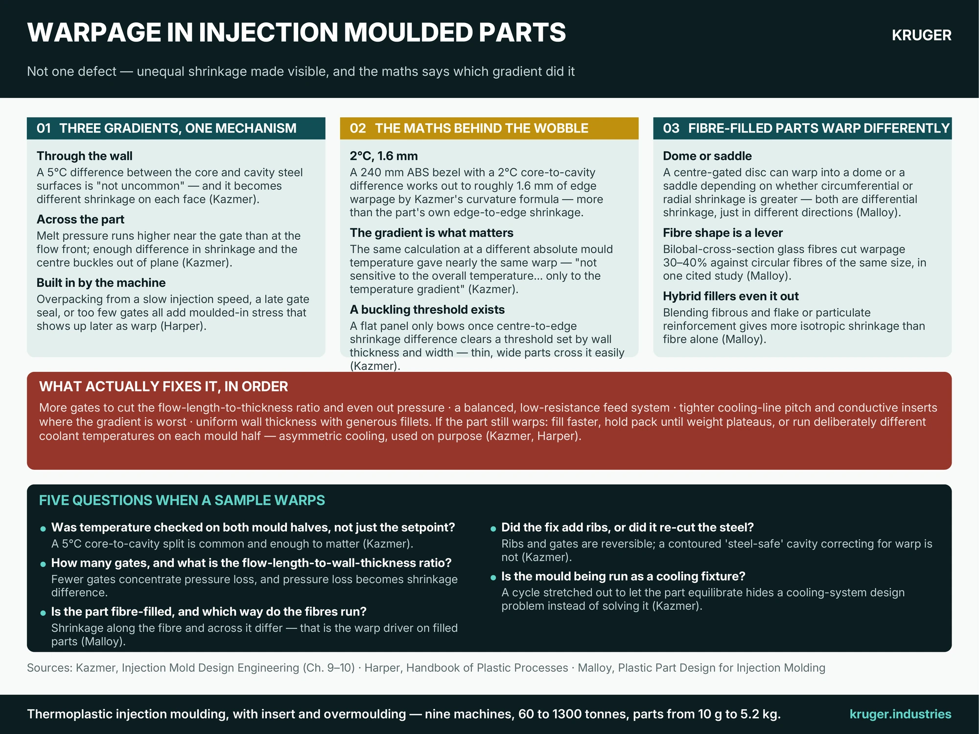
Kazmer’s mould-design textbook traces essentially all warpage back to differential shrinkage, and differential shrinkage back to one of three gradients. The simplest runs through the wall; as Kazmer puts it: “a temperature difference of 5 °C between surfaces of the core and the cavity inserts is not uncommon”, and any such split across the wall shows up directly as a split in shrinkage across the wall — the hotter face shrinks more, and the part curls toward it. The second runs across the part: melt pressure is higher near the gate than at the flow front, so a centre-gated part can shrink less in the middle than at the edges, and once the difference is large enough the centre buckles rather than staying flat. The third is built in by the machine, not the tool: Harper’s troubleshooting guide names an injection speed too fast or slow, a gate that has not sealed before the cavity fills, and too few gates as all adding “molded-in stresses in the part, which warp the part”.
The maths behind the wobble
Kazmer works a specific example: an ABS laptop bezel, 240 mm wide, with the mould’s cavity surface just 2 °C cooler than its core. The resulting difference in linear shrinkage — 0.31% against 0.34% — sounds trivial, but his curvature formula predicts roughly 1.6 mm of out-of-plane warpage at the part’s edge, more than the part’s own edge-to-edge shrinkage of 0.8 mm. The detail worth remembering: run the same analysis at a different absolute mould temperature and the predicted warp barely changes. As Kazmer points out, what drives the estimate is the difference between the two faces of the wall, not how hot the moulding is overall. Chasing warpage by adjusting an average setpoint, without checking whether the two halves match, tunes the wrong variable.
Fibre-filled parts warp differently
Malloy’s part-design handbook adds a wrinkle that matters the moment glass or mineral fibre reinforcement enters the material. In a centre-gated part filling by radial flow, differential shrinkage between the flow direction and the cross-flow direction can produce either a dome or a saddle shape. Malloy’s rule of thumb is that “dome like warpage is likely to occur when the circumferential mold shrinkage is greater than the radial mold shrinkage”; reverse the relationship — radial shrinkage higher than circumferential, or the inner region of the part shrinking more than the outer — and Malloy expects a saddle instead. Both are the same underlying mechanism, warping in different directions. Fibre geometry is itself a lever: Malloy cites a study in which bilobal, rather than circular, glass fibres “resulted in a 30-40% reduction in warpage” at similar mechanical performance, and he notes that hybrid composites blending fibrous with flake filler shrink more evenly in every direction than fibre alone — useful where a filled part needs a tight flatness tolerance.
What actually fixes it, in order
Kazmer’s own prescription starts at the mould-design stage, not the machine settings: use enough gates to avoid a high flow-length-to-wall-thickness ratio, design a balanced, low-resistance feed system so cavity pressure stays uniform, hold the cooling-line pitch tight with conductive inserts where the gradient runs worst, and keep wall thickness uniform with generous fillets. If a part is already warping, the next levers sit at the machine: fill faster to reduce cooling in the solidifying skin, hold packing pressure until part weight stops increasing, or run deliberately different coolant temperatures on each side of the mould. Harper’s version of that last lever is simple to apply on the shop floor: a part bows towards the hotter half because that side shrinks more, so for semicrystalline resins — polypropylene, nylon, polyethylene — you cool down the half the part is bending towards until it straightens. Only once these are exhausted does Kazmer recommend cutting into the steel: more gates first, then added ribs for stiffness, and — as a last, expensive resort — contouring the cavity so the part straightens as it warps, an approach that Kazmer says “places a significant burden on the mold designer and mold maker” and that becomes very costly indeed if the warpage prediction turns out to be wrong.
What a warped sample tells you about your moulder
- Was the mould-half temperature actually measured, not just set? A 5 °C core-to-cavity split is common enough that Kazmer calls it unremarkable — and enough to matter.
- How many gates, and what is the flow-length-to-wall-thickness ratio? Fewer gates concentrate pressure loss into a bigger shrinkage difference.
- Is the material fibre-filled, and does the gate layout control fibre orientation? Shrinkage along the fibre direction and across it are genuinely different numbers.
- Did the fix add gates or ribs, or did it recut the cavity surface? The first two are reversible and comparatively cheap; the third is not.
- Is the cycle being run long specifically to let the part cool evenly? A stretched cycle that compensates for an uneven mould is a cooling-system design problem wearing a process-parameter disguise.
Our design for mouldability and cooling time guides cover the upstream decisions — wall thickness, gating, cooling-line layout — that keep a part out of this article in the first place; our quality paper trail covers how a first-article inspection catches a warping tendency before a production run does. Send the drawing and tell us the flatness tolerance that actually matters on the part — that is the number a gating and cooling plan gets designed around.
Sources quoted: C. A. Harper (ed.), Handbook of Plastic Processes (Wiley, 2006); D. O. Kazmer, Injection Mold Design Engineering (Hanser, 2007); R. A. Malloy, Plastic Part Design for Injection Molding (Hanser).