
/ KNOWLEDGE · DESIGN
Ultrasonic Welding of Plastic Parts: A Buyer’s Guide
Ultrasonic welding of plastic parts joins two mouldings for good, with no screw, clip or glue, and it has to be chosen before the tool is cut. The joint is not added afterwards: a small ridge on one half and a locating step on the other are moulded in. So the choice between screws, a snap fit, a weld, a heat stake and an adhesive belongs on the drawing you send for a quotation.
Five ways to join two halves
- Screws. The joint that opens for service; see our threaded inserts guide.
- Snap fit. Opens by hand with no hardware, but carries light loads only; see our snap-fit guide.
- Ultrasonic weld. Permanent, clean and quick, with nothing to buy for each part. It cannot be opened without breaking the housing.
- Heat stake. A moulded stud passes through a hole in the mating part and its end is melted into a head, like a rivet. The lock is mechanical, so it can hold a metal plate or a part in another plastic.
- Adhesive or solvent. Slower, and polypropylene and polyethylene are very hard to bond this way.
How the weld is made
A metal horn presses one half against the other and vibrates it. Friction melts a little plastic at the joint, the vibration stops and the melt freezes under pressure. Rosato’s handbook gives the frequency as 20 to 40 kHz and the whole weld as normally under two seconds. Done well, the joint can be about as strong as the plastic round it.
Which plastics weld well
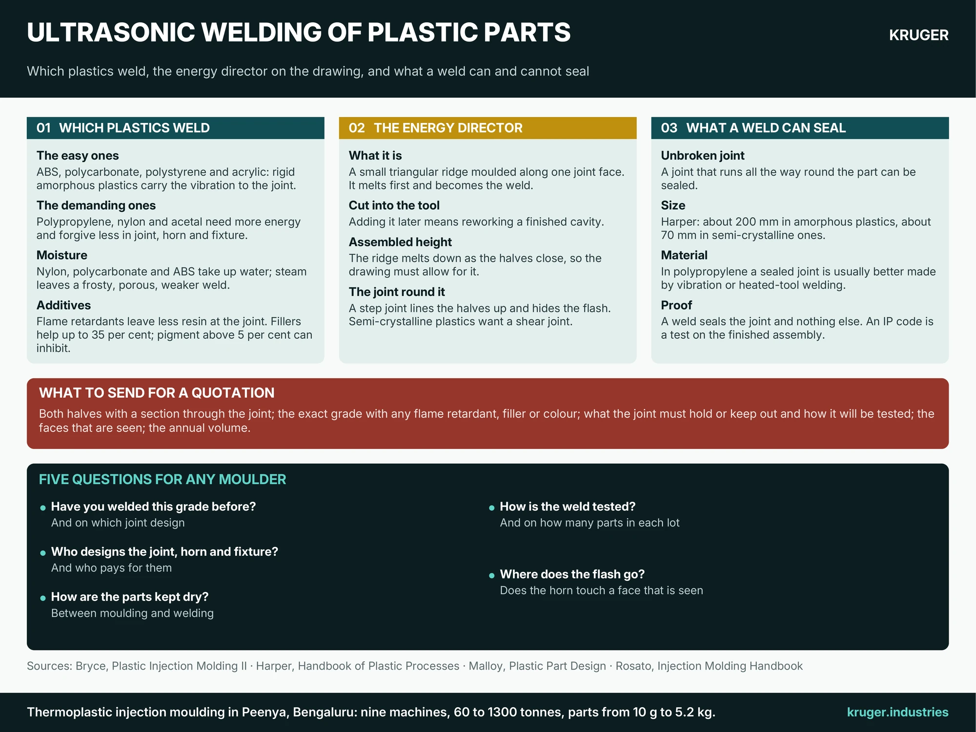
Rigid amorphous plastics are the easy ones: ABS, polycarbonate, polystyrene and acrylic soften gradually and carry the vibration to the joint. Semi-crystalline plastics such as polypropylene, nylon and acetal absorb part of the vibration and melt sharply, so they need more energy and are far less forgiving of the joint, the horn and the fixture. Soft, flexible grades damp the vibration and may not weld at all. The same grade in both halves is the safe choice.
The grade matters as much as the family. Bryce’s product-design volume lists what gets in the way.
- Moisture. Nylon, polycarbonate and ABS take up water, which turns to steam in the joint and leaves a frosty, porous, weaker weld. Weld parts straight from the machine or keep them sealed and dry.
- Flame retardants. They leave less weldable resin at the joint, so the joint must be larger and the energy higher. Say so if your enclosure or exit-sign housing is in a flame-retardant grade.
- Fillers and glass. Mineral fillers stiffen the part and help the weld up to a loading of 35 per cent. Above that there may be too little resin at the joint for a reliable seal.
- Pigment and release agent. A pigment loading above 5 per cent can inhibit the weld; so can mould release on the joint face.
The energy director, and why it must be on the drawing
An energy director is a small triangular ridge moulded along one joint face. Only its tip touches the other half, so the vibration is concentrated on a line: the ridge melts first, flows across the joint and becomes the weld. Leave it out and the energy spreads over the whole face: the weld takes longer and squeezes out an untidy bead.
It belongs on the drawing for three reasons. The ridge is cut into the tool steel, so adding it later means reworking a finished cavity. It melts down as the halves close, so the assembled height changes and the drawing must allow for it. And the joint round it has work to do: a step joint lines the halves up and hides the flash. Semi-crystalline plastics usually want a different detail, a shear joint, in which one half is a slight interference fit in the other and melts along the wall as the two telescope together. Either way the horn should land on a flat face directly above the joint. Sizes are settled with the welding-equipment maker; the drawing must carry the joint section and the faces the horn may touch.
What ultrasonic welding of plastic parts can and cannot seal
A joint that runs unbroken all the way round the part can be sealed. Three limits apply.
- Size. The horn sets it. Harper’s handbook puts the largest part at about 200 mm in amorphous plastics and about 70 mm in semi-crystalline ones. Larger housings can be spot welded, but a row of spots does not seal.
- Material. In polypropylene a sealed joint is usually better made by vibration or heated-tool welding. That is why our battery box guide lists a heat-sealed lid among the closures and not an ultrasonic weld.
- Proof. A weld seals the joint and nothing else. Cable entries and vents need their own seals, and an IP code is a test on the finished assembly, as our enclosure specification guide explains. State the test and the sample size.
Of the plastics on our materials list, ABS and polycarbonate are the easy pair; polypropylene and glass-filled nylon are the demanding pair.
Five questions for any moulder
- Have you welded this grade before, and on which joint design?
- Who designs the joint, the horn and the fixture, and who pays for them?
- How are the parts kept dry between moulding and welding?
- How is the weld tested, and on how many parts in each lot?
- Where does the flash go, and does the horn touch a face that is seen?
Ultrasonic welding is among the secondary operations on our capabilities page, so ask for the weld to be quoted with the mouldings. Send both halves through our RFQ page with a section through the joint, the exact grade with any flame retardant, filler or colour, what the joint must hold or keep out and how it will be tested, the faces that are seen, and the annual volume. If you have not chosen between a weld, a snap fit and screws, say so.
Sources quoted: D. M. Bryce, Plastic Injection Molding, Vol. II: Material Selection and Product Design Fundamentals (Society of Manufacturing Engineers, 1997); C. A. Harper (ed.), Handbook of Plastic Processes (Wiley, 2006); R. A. Malloy, Plastic Part Design for Injection Molding (Hanser, 1994); D. V. Rosato, D. V. Rosato and M. G. Rosato (eds), Injection Molding Handbook, 3rd edition (Kluwer Academic Publishers, 2000).